Tool for Multi-Technology Distributed Antenna Systems

a distributed antenna and multi-technology technology, applied in the direction of network planning, electrical equipment, radio/inductive link selection arrangements, etc., can solve the problems of serious deterioration of the network, limited radio frequency penetration, and complex indoor rf design, so as to improve the design process, and improve the effect of the disposition

Inactive Publication Date: 2008-01-31
IBWAVE SOLUTIONS
View PDF9 Cites 106 Cited by
  • Summary
  • Abstract
  • Description
  • Claims
  • Application Information

AI Technical Summary

Benefits of technology

[0012] Another important aspect of the present invention is to provide a computerized design tool for designing DAS networks wherein the computerized design tool is able to execute simultaneous complex RF calculations in the uplink and / or downlink directions for each selected band of frequencies and for each selected communication technology.
[0014] Yet another aspect of the present invention is to provide a computerized design tool for designing DAS networks which provides substantially real-time validation of the design and which also provide substantially automatic troubleshooting.
[0017] The aforesaid and other objectives of the present invention are realized by generally providing a novel design tool for designing distributed antenna systems (DAS) networks. As mentioned above, a DAS network is generally the portion of the network between the signal sources (i.e. the base stations) and the remote antennas. Since different signal sources can use different communication technologies and / or different bands of frequencies, it is important for a modem DAS network to support all the technologies and / or bands of frequencies of the signal sources to which it is connected. Hence, the design tool of the present invention is adapted to do simultaneous complex RF calculations in the uplink and / or downlink direction for all the defined signal sources to which the DAS network is connected. The present invention reduces the difficulties and disadvantages of the prior art by providing a design tool which enables the wireless designers to use one common tool to design and select the right components, evaluate and adjust a wireless DAS network.
[0019] Thus, the present design tool allows the wireless designer to define the signal sources which the DAS network will have to support. Being essentially a computer-aided design tool, the definition of the signal sources is preferably effected through menus and input windows into which the specific parameters of each signal source are entered. Once all the signal sources are defined, the wireless designer can start designing the DAS network.
[0024] The results of these calculations are simultaneously displayed at each interconnection of each antenna and each network component present on the design window, thereby significantly reducing design errors and enabling DAS components' incompatibilities to be detected and corrected rapidly. Additionally, the design tool advantageously comprises a debug message window into which all the components' incompatibilities are listed, thereby allowing the wireless designer to see at a glance which antenna and / or network component and / or cable element are incompatible for certain bands of frequencies and / or for certain technologies.
[0026] In order to enhance the design process, the design screen of the design tool preferably provides graphical and schematic views of the design. These detailed graphical and schematic views advantageously improve the design process by increasing the understanding of the disposition of each antenna, each network component, each cable element and each source of signals of the DAS and the relation between them.

Problems solved by technology

With the new form factor of cellular phones and the growing demand for wireless data services, the mobile traffic has shifted from outdoors to indoors, where typically radio-frequency (RF) penetration is often limited.
Indoor RF design is generally very complex, especially nowadays with the advent of multi-operators and multi-technologies that are requested by the building's owners.
These systems can cause serious deterioration of the network if they are not engineered correctly.
Moreover, wireless operators may suffer from a lack of knowledge and expertise and may not take full advantage of their indoor networks.
However, the main focus of these design tools generally revolves around propagation prediction, which is not adequate for efficient network design.
Moreover, the aforesaid design tools are only predicting the coverage between the antennas and the mobiles without taking into account the distributed antenna system (DAS) network that interfaces the base stations with those antennas.
Another important limitation of those tools is that they are predicting only one band of frequency at the time which is not reflecting today's requirements.
These methods tend to be error prone, complicated and not standard from one designer to another.

Method used


Image

  • Tool for Multi-Technology Distributed Antenna Systems
  • Tool for Multi-Technology Distributed Antenna Systems
  • Tool for Multi-Technology Distributed Antenna Systems

Examples


Embodiment Construction

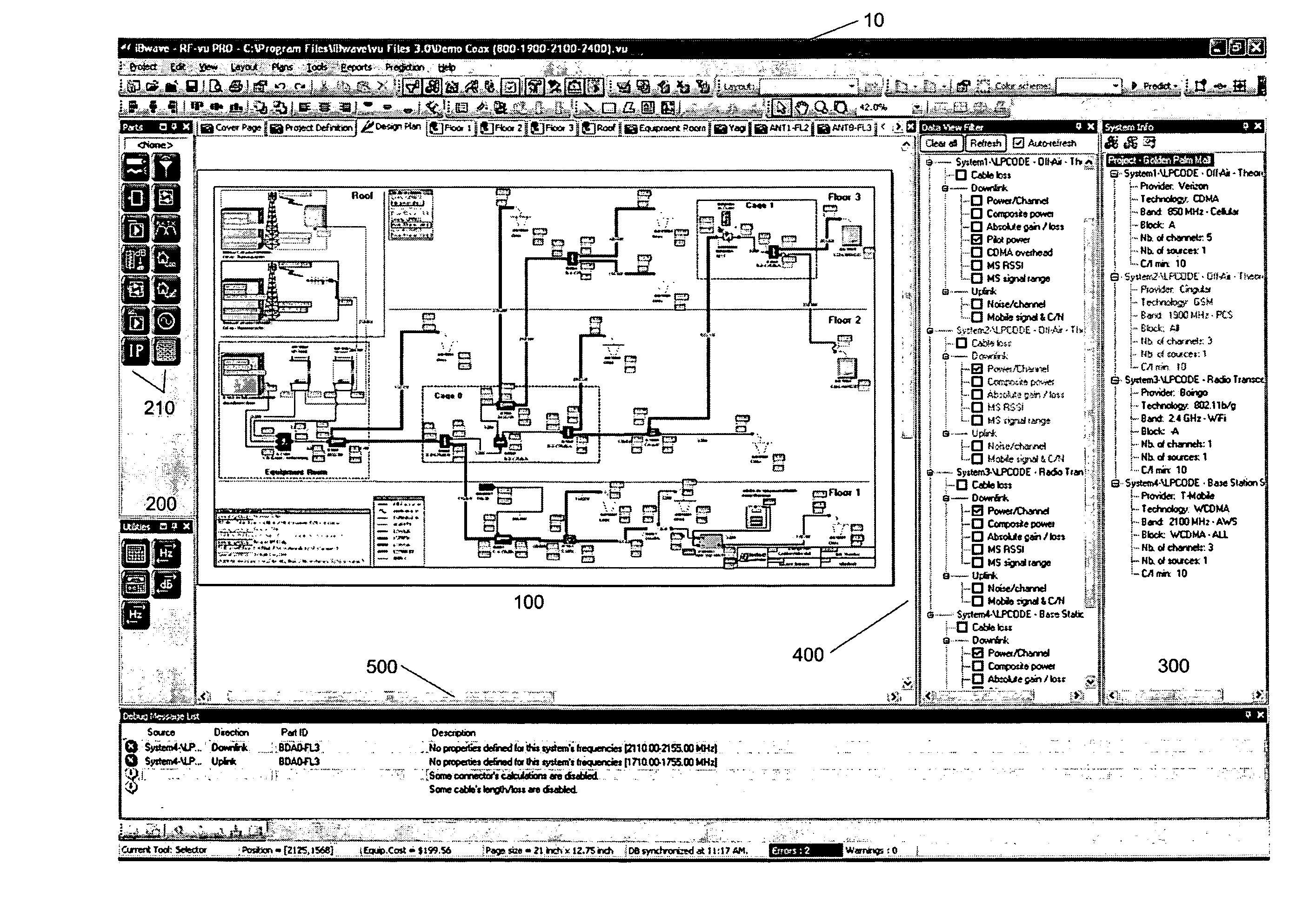
[0044] A novel design tool for multi-technology distributed antenna systems will be described hereinafter. Although the invention is described in terms of specific illustrative embodiments, it is to be understood that the embodiments described herein are by way of example only and that the scope of the invention is not intended to be limited thereby.

[0045] In a nutshell, the design tool of the present invention allows the wireless designer to devise a DAS network which can support multiple signal sources, each of them possibly using a different band of frequencies and / or a different communication technology. Moreover, for each compatible signal source present in the design, the design tool substantially simultaneously computes uplink and downlink values at each antenna and each network component interconnection. Also, the design tool updates any uplink and / or downlink calculations which may have been affected by a modification in the design.

[0046] Being a computer-aided design (CA...


PUM


Abstract

A computer-implemented design tool is disclosed for designing a multi-technology wireless Distributed Antenna Systems (DAS) network. The design tool allows a wireless designer to select antennas, network components, cable elements and signal sources from one or more databases and to place them on a design screen. The design tool is particularly configured to create DAS network adapted to support several signal sources, each signal source generally using a different band of frequencies and / or a different wireless network communication technology. In addition, the design tool performs multiple simultaneous complex RF calculations in uplink and / or downlink direction for each signal source and further displays the results of these calculations at each interconnection of the DAS network. The design tool also updates all the RF calculations when the network design is modified by the designer. Hence, by performing and updating RF calculations for several bands of frequencies and several communication technologies, the design tool allows the designer to rapidly correct the flaws in his design in order to rapidly obtain an adequate network design.

Description

CROSS-REFERENCE TO RELATED APPLICATIONS [0001] The present patent application is a continuation-in-part of commonly assigned U.S. patent application Ser. No. 10 / 744,018, now abandoned, and claims the benefits of priority thereof. The disclosure of U.S. patent application Ser. No. 10 / 744,018 is incorporated herein by reference.FIELD OF THE INVENTION [0002] The present invention generally relates to wireless communications networks, and more particularly to a system and method for designing wireless communications networks. BACKGROUND OF THE INVENTION [0003] Mobile communications devices, such as cellular telephones, pagers and the like, are now commonplace and are now being used more indoor than in vehicles. With the new form factor of cellular phones and the growing demand for wireless data services, the mobile traffic has shifted from outdoors to indoors, where typically radio-frequency (RF) penetration is often limited. To maximize ARPU (Average Revenues Per Users), reduce the per...

Claims


Application Information

Patent Timeline
Patent Type & Authority Applications(United States)
IPC IPC(8): H04Q7/20H04W16/18H04W16/20
CPCH04W16/20H04W16/18
Inventor CHARBONNEAU, HUGO
Owner IBWAVE SOLUTIONS
Why Eureka
Try Eureka