
Method for improved retinal safety using the light adjustable lens (LAL)

Inactive Publication Date: 2008-01-31
CALHOUN VISION INC
View PDF4 Cites 88 Cited by
  • Summary
  • Abstract
  • Description
  • Claims
  • Application Information

AI Technical Summary

Benefits of technology

[0005]Embodiments of the invention involve intraocular lenses that are capable of having their refractive power modified in-vivo by irradiation with the appropriate dose, spatial irradiance profile, and frequency of light. This novel type of intraocular lens is known as the light adjustable lens (LAL). The LAL consists of four basic components. The first is the matrix polymer, which gives the LAL its basic optical and mechanical properties. Homogeneously distributed throughout the matrix polymer is a chemical moiety referred to as the macromer. The macromer contains photopolymerizable endgroups that are capable of forming crosslinks between each other if it is exposed to light of the appropriate frequency. The third major component is the photoinitiator, which initiates the macromer crosslinking by forming highly reactive radicals after absorbing light of the appropriate frequency. The fourth major component is the UV absorber which acts to protect the retina from UV light. More extensive details regarding the chemical composition and mechanism for refractive power change can be found in the literature (U.S. Pat. Nos. 6,560,642, 6,721,043, 6,749,632, and 6,813,097, incorporated herein by reference). The typical wavelength(s) of light that is used to adjust the refractive power of the LAL is in the near-UV (e.g. 365 nm). After the LAL has been adjusted to the desired refraction it is typically necessary to perform a final photolocking step which involves irradiating the entire lens which consumes substantially all the remaining macromer. During photolocking some UV light may unintentionally spill over the outside edges of the LAL due to normal eye movement, variation in anterior chamber distance (ACD) of the LAL (i.e. magnificiation differences), and a dimensional difference in the lens from the manufactured process. Due to the potentially hazardous effects of UV light to the eye, particularly the retina, it is desirable to find solutions that permit the LAL to be locked-in while at the same time minimizing the amount of light striking the retina.
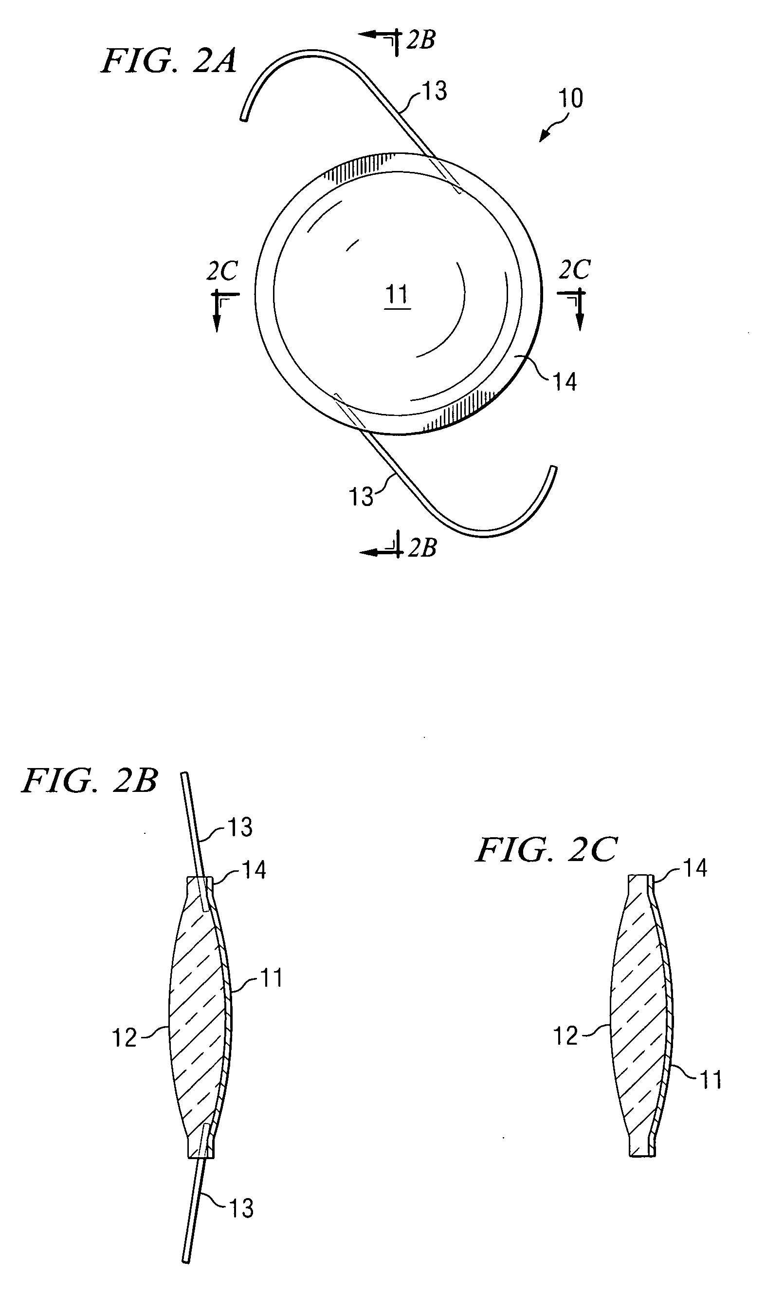
[0006]To prevent or reduce the amount of UV light striking the retina, the LAL, according to embodiments of the invention, includes a layer of UV absorbing material located on its posterior surface, i.e. the side facing the retina. Other embodiments include having the lens comprise a UV reducing rim that surrounds the peripheral portion of the lens, and reduces or blocks UV light from striking the retina. The rim may comprise a material that absorbs, reflects, and / or scatters the UV light. The rim may also comprise a structure such as frosting or a grating that scatters or diffracts the UV light.
[0007]One feature of an embodiment of the invention is to significantly enhance UV safety for patients using light adjustable intraocular lens.
[0008]Another feature of an embodiment of the invention is that the UV layer and / or the UV rim do not require in-vivo lock-in.
[0010]A still further feature of an embodiment of the invention is that the UV layer and / or the UV rim assists in the prevention of cells from migrating to the back of the LAL, which leads to an improved PCO rate. The PCO rate can be significantly reduced using sharp-edged lens designs that involve certain pressure to the posterior capsule. The additional UV safety rim may be advantageously shaped in the form of a sharp edge design of particular angulations.

Problems solved by technology

During photolocking some UV light may unintentionally spill over the outside edges of the LAL due to normal eye movement, variation in anterior chamber distance (ACD) of the LAL (i.e. magnificiation differences), and a dimensional difference in the lens from the manufactured process.

Method used


Image

  • Method for improved retinal safety using the light adjustable lens (LAL)
  • Method for improved retinal safety using the light adjustable lens (LAL)
  • Method for improved retinal safety using the light adjustable lens (LAL)

Examples


Embodiment Construction

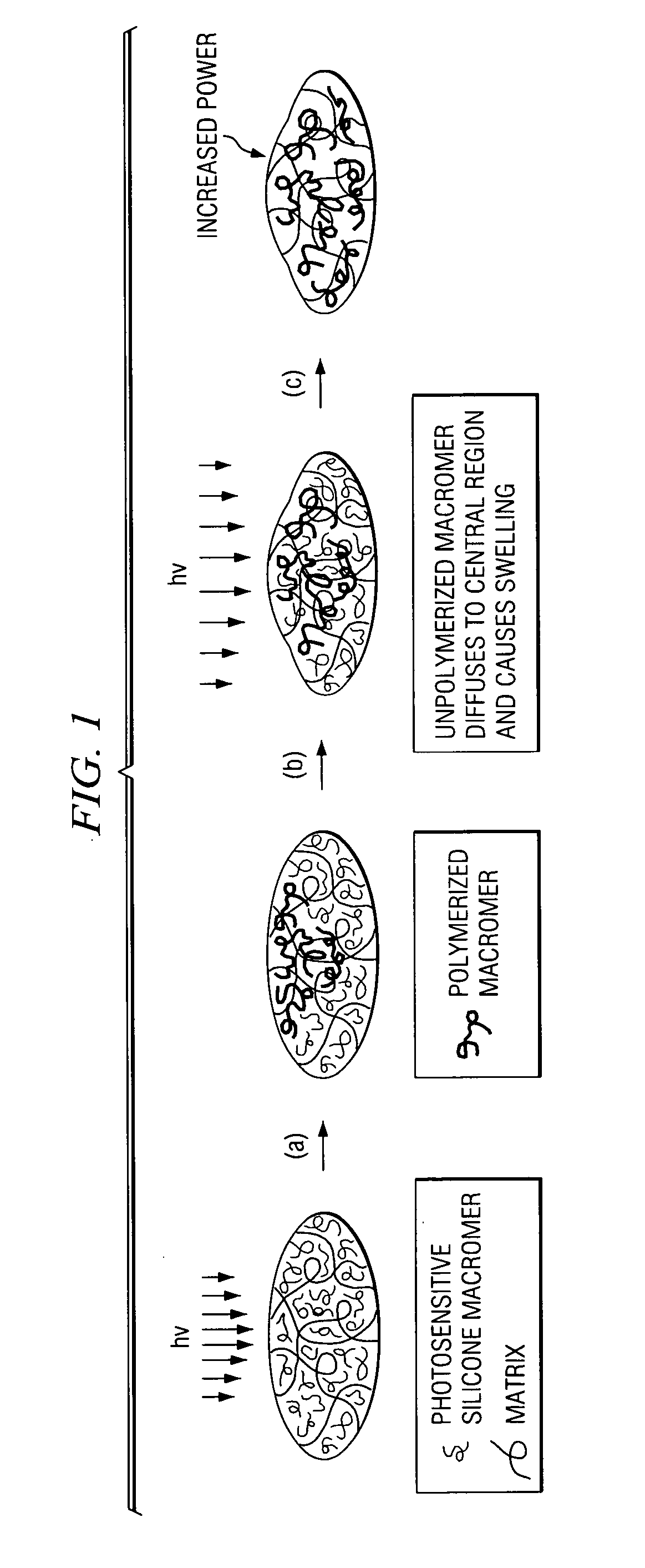
[0023]A light adjustable lens (LAL) comprises four distinct chemical entities or components. The first component is the matrix polymer that gives the lens its basic shape, refractive index, and material properties. The second component is known as the macromer and is, by design, chemically similar to the matrix polymer. One difference between the two is the presence of photopolymerizable end groups on the macromer such that the application of the appropriate frequency of light will cause the macromer molecules to form chemical bonds between each other. The third component is the photoinitiator that absorbs the applied incoming light (365 nm) and initiates polymerization of the macromer. The fourth component of the LAL is a UV absorbing molecule that protects that retina from ambient UV irradiation.

[0024]The mechanism upon which the LAL technology is based is depicted graphically in FIG. 1. Application of light to-the LAL will cause the photopolymerized macromers in the irradiated re...


PUM


Abstract

Embodiments of the invention involve intraocular lenses that are light adjustable to change a focal length of the lens after it has been implanted into a person or animal. The lens includes a layer of UV absorbent material located on a rear side, which is the side facing a retina. The lens may comprise a UV reducing rim that surrounds a peripheral portion of the lens, and reduces or blocks UV light from striking the retina.

Description

CROSS-REFERENCE TO RELATED APPLICATIONS[0001]This application is related to co-pending and commonly assigned U.S. patent application Ser. No. 10 / 319,082, filed Dec. 13, 2002, and published as 2003 / 0176521, on Sep. 18, 2003, entitled “INITIATOR AND ULTRAVIOLET ABSORBER FOR CHANGING LENS POWER BY ULTRAVIOLET LIGHT,” and U.S. Patent Application Ser. No. 60 / 715,310, filed Sep. 8, 2005, entitled “NOVEL ADJUSTABLE OPTICAL ELEMENTS WITH ENHANCED UV PROTECTION,” the disclosures of which are hereby incorporated herein by reference.TECHNICAL FIELD[0002]This application relates in general to intraocular lenses, and in specific to intraocular lenses that are capable of post-operative modification of their optical properties and to intraocular lenses that can be modified in-vivo by exposing them to radiation.BACKGROUND OF THE INVENTION[0003]Cataract extraction followed by intraocular lens (IOL) implantation is the most commonly performed surgery in patients over 65 years old. See, Learning, D. V...

Claims


Application Information

Patent Timeline
IPC IPC(8): A61F2/16
CPCA61F2/1618A61F2/1635G02C2202/14A61L2430/16A61L27/50
Inventor GERLACH, MARIOSANDSTEDT, CHRISTIAN A.CHANG, SHIAO H.
Owner CALHOUN VISION INC
Learn More