Electric power steering apparatus

a technology of electric power steering and steering apparatus, which is applied in the direction of steering initiation, instruments, vessel construction, etc., can solve the problems that the prior art cannot cope with the change in the joint angle (crossing angle) of an electric or manual tilting mechanism, the problem of not being able to solve the problem, and the change in the manual input by steering of the driver, so as to prevent the thrust exceeding the maximum rack thrust and reduce the change in the manual input by steering the driver.

Inactive Publication Date: 2008-01-31
NSK LTD
View PDF4 Cites 54 Cited by
  • Summary
  • Abstract
  • Description
  • Claims
  • Application Information

AI Technical Summary

Benefits of technology

[0010]In view of the first problem, one object of this invention is to provide an electric power steering apparatus which can detect a torque fluctuation due to changes in a joint angle (crossing angle) and control the motor so as to cancel the torque fluctuation. Another object of this invention is to provide an electric power steering apparatus which can reduce changes in a manual input by steering of a driver even where the thrust becomes insufficient because of the torque fluctuation due to changes in the tilting angle. Still another object of this invention is to provide an electric power steering apparatus which can execute the motor control according to a torque fluctuation so that the thrust exceeding the maximum rack thrust of the electric power steering apparatus is not applied to the rack.
[0011]Further, in view of the second problem, another object of this invention is to make torque control according to a torque fluctuation due to changes in a cardan universal joint angle. Another object of this invention is to reduce changes in a manual input by steering of a driver even where the thrust becomes insufficient because of the torque fluctuation due to changes in the tilting angle. Still another object of this invention is to implement the motor driving according to the torque fluctuation so that the thrust exceeding the maximum rack thrust of the electric power steering apparatus is not applied to the rack.
[0055]In accordance with the first through sixth aspects of this invention, the torque fluctuation due to changes in the tilting angle of the steering shaft is detected on the basis of the steering angle and any one of the steering torque, current command value and self-aligning torque and the current correction value is correspondingly computed. For this reason, without detecting the tilting angle, changes in a manual input by steering of a driver can be reduced.
[0056]Further, the steering assistant force generated in the electric motor can be effectively used to the utmost while surely preventing the thrust exceeding the maximum permissible torque in the electric power steering apparatus from being supplied to the torque transmitting system.
[0057]In accordance with the seventh through twelfth aspects of this invention, the torque control corresponding to a torque fluctuation due to a change in a cardan universal joint angle can be executed. Further, in accordance with this invention, even if a shortage of the thrust is generated by the torque fluctuation due to the change in the tilt angle, a change in the manual input due to steering by the driver can be reduced. Further, in accordance with this invention, it is possible to prevent the thrust exceeding the maximum rack thrust of the electric power steering apparatus from being applied to the rack. In addition, the motor output can be effectively used to the utmost.

Problems solved by technology

So, as the case may be, the prior art cannot cope with changes in the joint angle (crossing angle) by an electric or manual tilting mechanism.
However, if changes in the joint angle (crossing angle) cannot be detected or a necessary rack thrust exceeds the maximum thrust of the motor, because of shortage of thrust, changes in a manual input by steering of the driver occurs.
This problem has not been yet solved.
So, as the case may be, the related art cannot cope with changes in the joint angle (crossing angle) by an electric or manual tilting mechanism.
However, if a necessary rack thrust exceeds the maximum thrust of the motor, because of shortage of thrust, changes in the manual input by steering of the driver occurs.

Method used


Image

  • Electric power steering apparatus
  • Electric power steering apparatus
  • Electric power steering apparatus

Examples


first embodiment

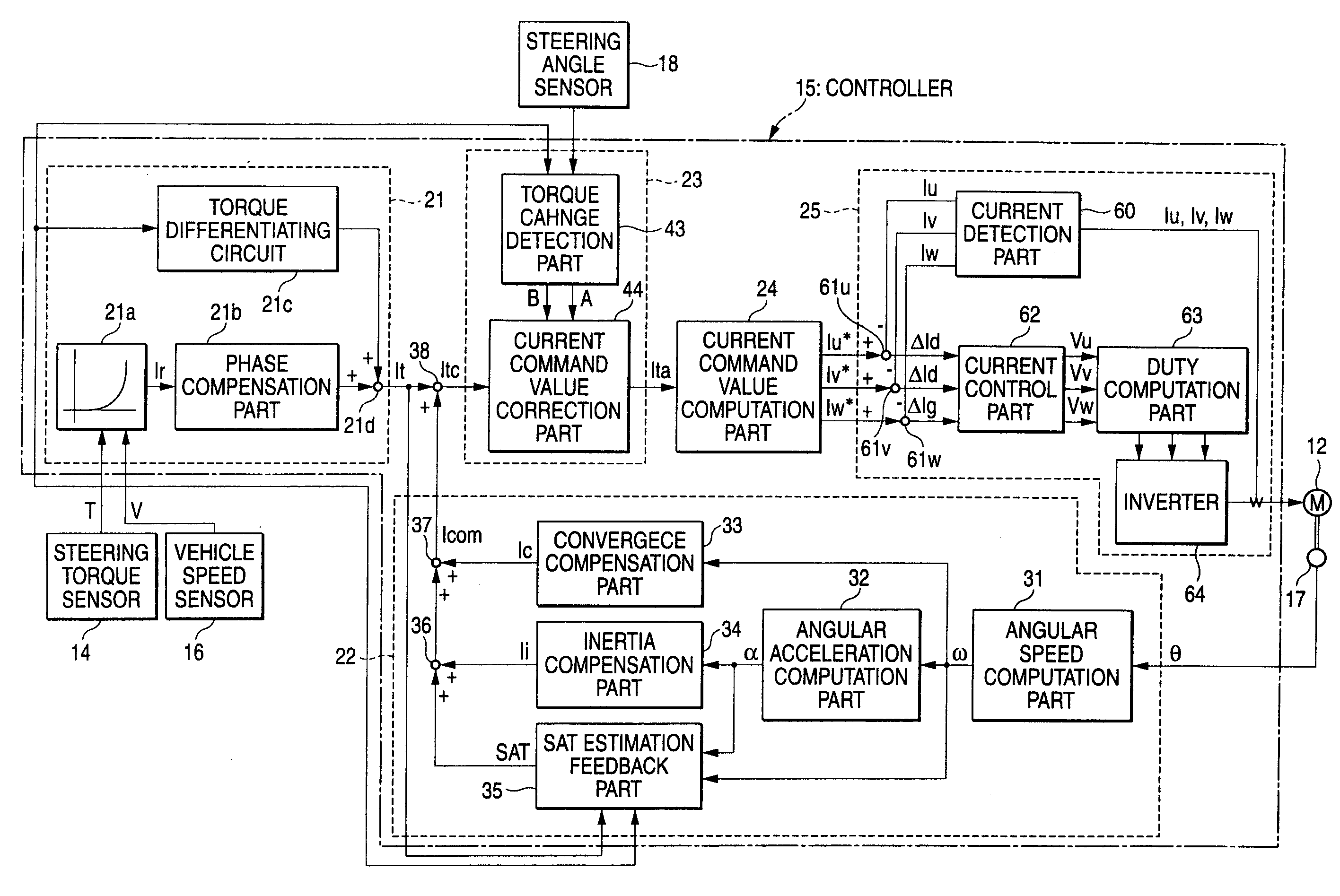
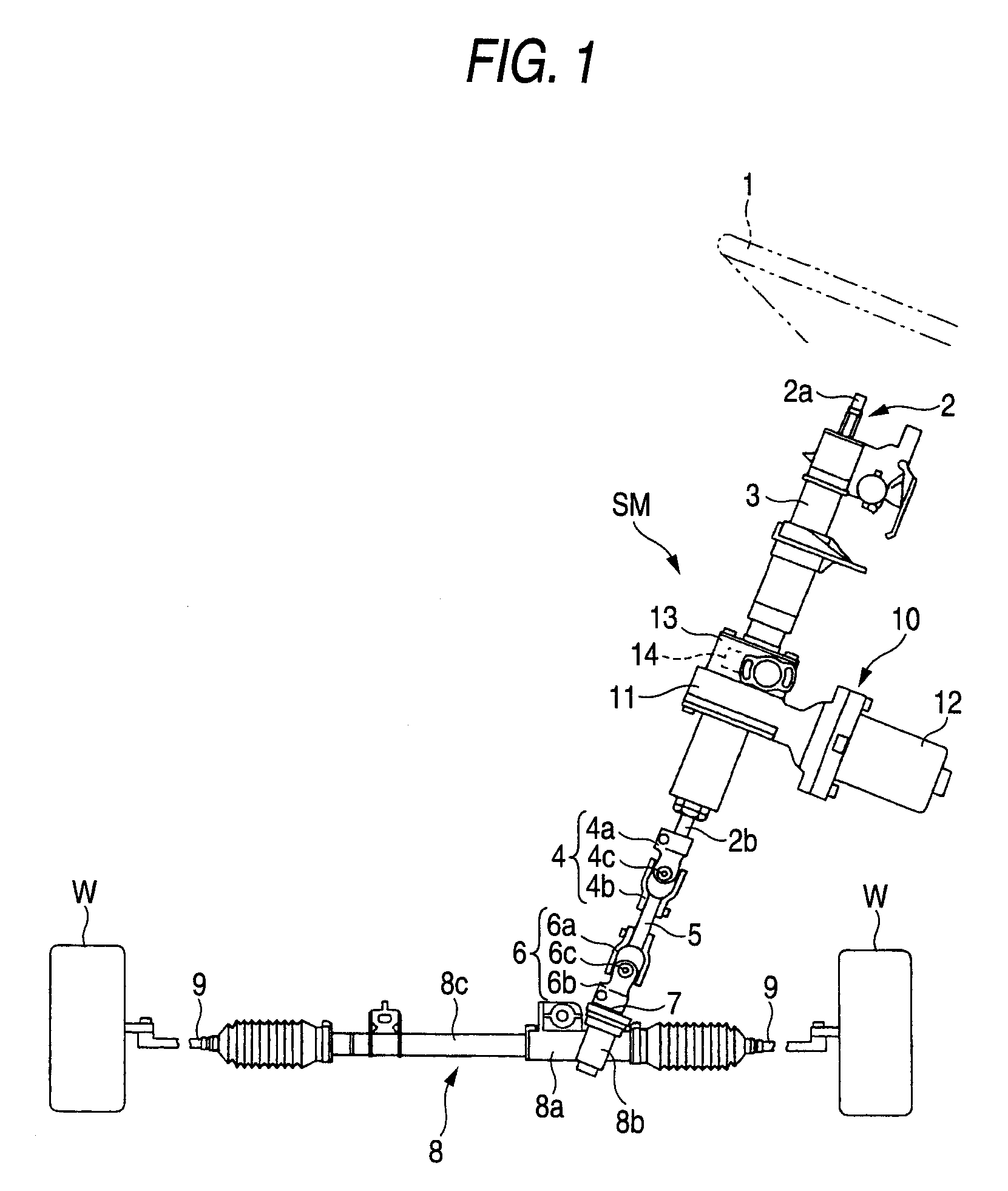
[0090]FIG. 1 is a view showing the schematic configuration of the electric power steering apparatus according to the first embodiment of this invention.

[0091]In FIG. 1, symbol SM refers to a steering mechanism. This steering mechanism SM is provided with a steering shaft 2 having an input shaft 2a to which the steering force exerted to a steering wheel 1 by a driver is transmitted and an output shaft 2b coupled with the input shaft 2a through a torsion bar not shown. The steering shaft 2 is rotatably mounted within a steering column 3. The one end of the input shaft 2a is connected to the steering wheel 1 and the other end thereof is connected to a torsion bar not shown.

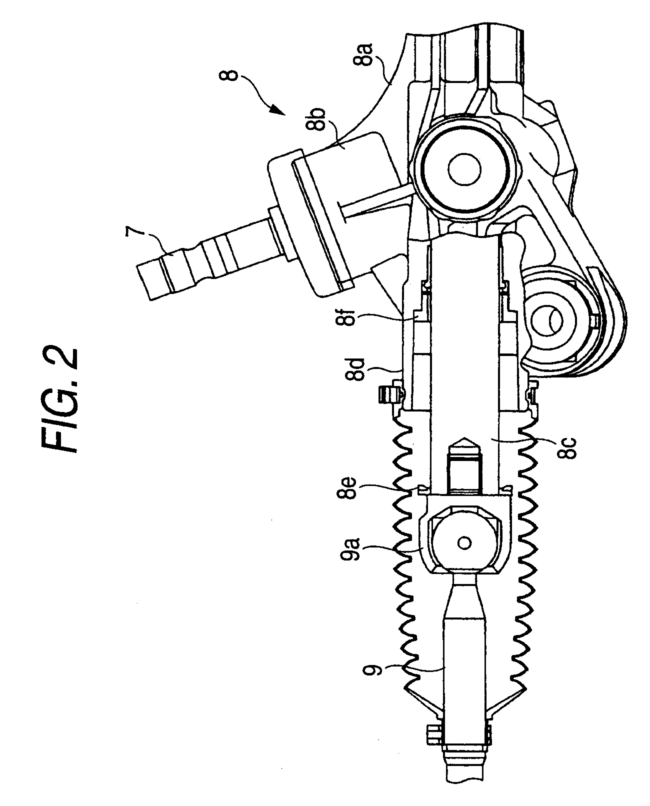
[0092]The steering force transmitted to the output shaft 2b is transmitted to an intermediate shaft 5 through a universal joint 4 consisting of two yokes 4a, 4b and a cross coupling segment 4c for coupling them. The steering force is further transmitted to a pinion shaft 7 through a universal joint 6 consisting of tw...

second embodiment

[0152]Next, referring to FIGS. 13 and 14, an explanation will be given of the second embodiment of this invention.

[0153]In this second embodiment, unlike the first embodiment in which the current command value is corrected in order to restrict the torque fluctuation, the current command value is limited so that the torque fluctuation generated in the universal joint is within the range of the maximum permissible torque of the torque transmission system.

[0154]Specifically, in the second embodiment, in the current correcting unit 23 in the first embodiment, as shown in FIG. 13, the cosine wave component computing unit 44b, multiplier 44c and adder 44d are omitted; and instead of this, the current correcting unit 23 includes a limited value computing unit 71 for computing a maximum current limited value I1t on the basis of the phase B and amplitude A detected by the amplitude / phase detecting unit 42 and a limiting unit 72 for receiving the compensated current command value Itc as well ...

third embodiment

[0175]Now, with referring to FIGS. 20 through 31, the third embodiment of the present invention which solves the above described second problem is explained.

[0176]FIG. 20 is a block diagram of the electric power steering apparatus according to the third embodiment of this invention. As seen from FIG. 20, an electric power steering apparatus 101 apparatus 10110 includes a torque sensor 112, a tilt sensor 114, an angle sensor 116, a control unit 118 and an electric motor 120. The electric power steering apparatus 101 is an electric power steering apparatus in which a manual or electric tilt angle adjusting mechanism and a cardan universal joint are included in a steering force transmitting system (not shown) connecting a steering shaft coupled with a steering wheel and a steering mechanism.

[0177]The torque sensor 112 detects steering torque which acts on a steering force transmitting system owing to a manual input by steering of a driver and supplies the steering torque thus detected ...


PUM


Abstract

An electric power steering apparatus has a steering mechanism SM having universal joints 4, 6 in a torque transmitting system, a steering toque detecting unit 14, a steering angle detecting unit 18, a torque fluctuation detecting unit 43 for detecting a torque fluctuation due to the crossing angle α in the universal joints 4, 6 on the basis of the steering angle θ detected by the steering angle detecting unit 18 and any one of the steering torque T detected by the steering torque detecting unit, a current command value It and self-aligning torque SAT; and a current command value correcting unit 44 for correcting the current command value on the basis of the torque fluctuation detected by the torque fluctuation detecting unit 43 and the steering angle θ detected by the steering angle detecting unit 18.

Description

BACKGROUND OF THE INVENTION[0001]1. Field of the Invention[0002]This invention relates to an electric power steering device designed to assist steering by controlling the drive of a steering assistant motor on the basis of steering torque due to steering of a steering wheel thereby to transmit the rotating force of the motor to a steering mechanism.[0003]2. Description of Related Art[First Problem][0004]In such an electric power steering apparatus which gives the steering assistant force generated by the electric motor to the steering mechanism having the universal joint in the torque transmitting system, a torque fluctuation due to the universal joint is generated. In order to restrict the torque fluctuation, there is a known electric power steering apparatus which acquires a correction coefficient corresponding to the steering angle of a steering shaft, computes a correction motor current command value on the basis of the correction coefficient and a motor current command value de...

Claims


Application Information

Patent Timeline
Patent Type & Authority Applications(United States)
IPC IPC(8): B62D5/04
CPCB62D5/0472B62D5/0463
Inventor AOKI, YUHOHARA, TAKESHIFURUSHIMA, NOBUHIROKOBAYASHI, HIDEYUKIENDO, SHUJI
Owner NSK LTD
Why Eureka
Try Eureka