Oil filling structure of internal combustion engine

Inactive Publication Date: 2008-02-07
HONDA MOTOR CO LTD
View PDF4 Cites 8 Cited by
  • Summary
  • Abstract
  • Description
  • Claims
  • Application Information

AI Technical Summary

Benefits of technology

[0006]An object of an embodiment of the present invention is to provide an oil filling structure that makes it

Problems solved by technology

In addition, the workability of

Method used


Image

  • Oil filling structure of internal combustion engine
  • Oil filling structure of internal combustion engine
  • Oil filling structure of internal combustion engine

Examples


Embodiment Construction

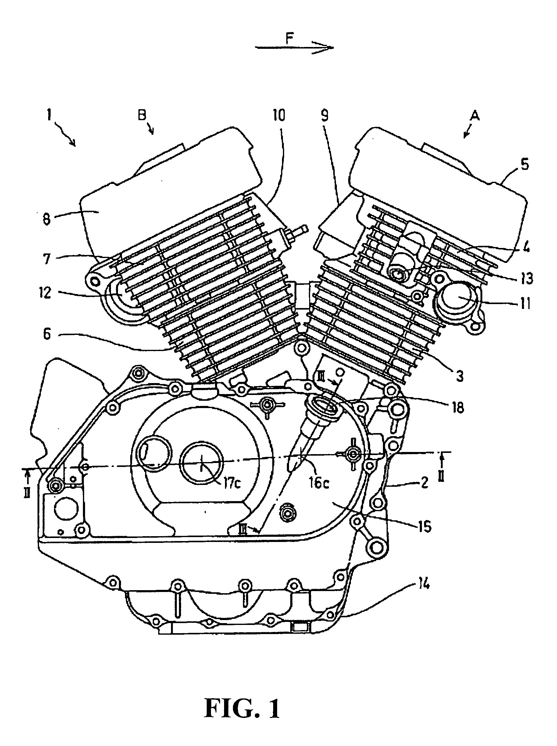
[0019]FIG. 1 is a side view of a V-type internal combustion engine 1 to which an oil filling structure of the present invention is applied. An arrow F indicates a forward traveling direction in a state wherein the internal combustion engine 1 is attached to a vehicle. The internal combustion engine is mounted on a motorcycle. A crankcase 2 is assembled onto an upper surface of which a front cylinder A composed of a cylinder block 3, a cylinder head 4, and a head cover 5, and a rear cylinder B composed of a cylinder block 6, a cylinder head 7, and a head cover 8. An inlet port 9 and an exhaust port 11 are provided on the front cylinder A. An inlet port 10 and an exhaust port 12 are provided on the rear cylinder B. A spark plug mounting hole 13 is provided on the front cylinder A. A spark plug of the rear cylinder B is provided on an opposite side surface to the spark plug 13 of the front cylinder A, and accordingly, is not shown.

[0020]An oil pan 14 is provided on a lower portion of t...


PUM


Abstract

In an internal combustion engine, an oil-filler-port/oil-level-gauge attachment hole is formed on a side of the internal combustion engine. An oil-level-gauge for measuring the amount of oil in the inside of the internal combustion engine extends within the oil-filler-port. The oil-level-gauge is formed integral with a cap for the oil-filler-port. A guide cylinder portion for guiding the gauge deep inside the oil-level-gauge attachment hole is provided to extend therein. A side outflow hole where the filled oil detours around the guide cylinder portion and directly flows down to the inside is formed on the way of the guide cylinder portion. A guide wall for preventing the gauge from entering the side outflow hole is formed on a lower portion of the side outflow hole.

Description

CROSS-REFERENCE TO RELATED APPLICATIONS[0001]The present application claims priority under 35 USC 119 to Japanese Patent Application No. 2006-210954 filed on Aug. 2, 2006 the entire contents of which are hereby incorporated by reference.BACKGROUND OF THE INVENTION[0002]1. Field of the Invention[0003]The present invention relates to an oil filling structure of an internal combustion engine including, on a side of the internal combustion engine, an oil-filler-port / oil-level-gauge attachment hole, and an oil-level-gauge integral with a cap of the oil-filler-port.[0004]2. Description of Background Art[0005]Heretofore, an oil-level-gauge has been short, and an oil-level-gauge attachment hole-oil-filler-port has been provided in a lower portion of an internal combustion engine. See, for example, Japanese Patent Application Laid-Open Publication No. 2003-97241. Therefore, a worker must take a low posture for checking the oil level and performing an oil filling operation. In addition, the w...

Claims


Application Information

Patent Timeline
IPC IPC(8): G01F23/04
CPCF01M11/12G01F23/04F01M2011/0491F01M11/0004F01M11/02F01M2011/0058
Inventor CHO, MASAKI
Owner HONDA MOTOR CO LTD
Why Eureka
Try Eureka