Apparatus and method for determining service life of electrochemical energy sources using combined ultrasonic and electromagnetic testing

a technology of electromagnetic testing and electrochemical energy sources, applied in the field of electrical engineering, can solve the problems of reducing the service life of the electrochemical energy source, affecting the operation of the device,

Inactive Publication Date: 2008-02-07
ENERIZE CORP
View PDF3 Cites 48 Cited by
  • Summary
  • Abstract
  • Description
  • Claims
  • Application Information

AI Technical Summary

Benefits of technology

[0033] Commutation or alignment of the transmitting ultrasonic probes is effected in series, along each array line. The signals of each receiving probe in the array are compared to all the neighboring probe signals that are arranged at a distance apart on the side of the square upon the grid of which the ultrasonic probes are arranged. Based on the comparison results, an operating group (set) of the pairs of transmitting and receiving probes are selected that to provide a sounding (image) of the operating region inside of the test object. In such case from the total number of the probe pairs, those pairs are excluded which are located beyond the test object limits. In this case the acoustic resistance values between the transmitting and the receiving probes are high. Additionally probe pairs are also excluded that are located close to the lateral edge of the battery, within the edge effect influence zone.

Problems solved by technology

With time and usage, the electrochemical energy devices mentioned above undergo a reduction in performance (degraded power and energy capacity).
This degradation occurs during storage and as a result of electrical energy generation, or of the charge-discharge cycling process in the case of batteries and supercapacitors.
In the process of lithium-ion battery operation (cycling and storage) the positive electrode material can be subject to different conditions within the interior and on the surface that lead to a deterioration of battery performance.

Method used


Image

  • Apparatus and method for determining service life of electrochemical energy sources using combined ultrasonic and electromagnetic testing
  • Apparatus and method for determining service life of electrochemical energy sources using combined ultrasonic and electromagnetic testing
  • Apparatus and method for determining service life of electrochemical energy sources using combined ultrasonic and electromagnetic testing

Examples


example 1

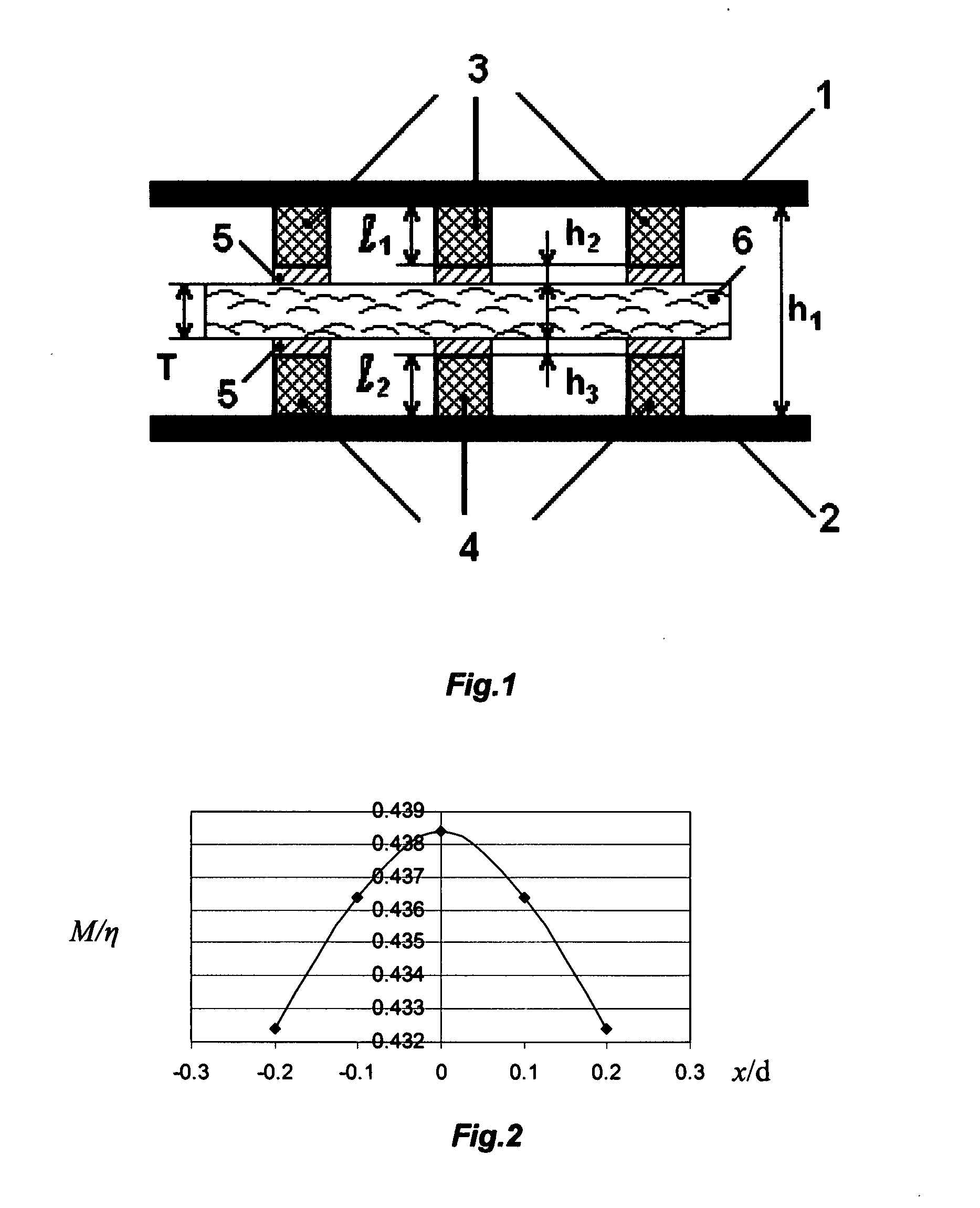
[0094] This example deals with the study of mutual induction changes in cylindrical coils of the orientation system that have parallel axes oriented in the direction of y during the shift of the coils in the radial direction along the axis x. The coils have an identical diameter d and an identical length a=2d, the distance between their adjacent end faces along the axis y is equal to d. The number of windings in the coils is identical and equals W. The mutual induction value M in conformity with [17] is calculated for our coils according to the formula: M=η⁡(X1b1-X2b2-X3b3+X4b4),(2)

where η=πμ0W2d / 256, Xk=[1-14⁢K1⁢ξk2⁢P2⁡(γk)+18⁢K2⁢ξk4⁢P4⁡(γk)-564⁢K3⁢ξk6⁢P6⁡(γk)+7128⁢K4⁢ξk8⁢P8⁡(γk)-…],⁢ξk=d2⁢ ⁢bk,γk=ckbk,bk=x2+ck2,c1=y-a,c2=c3=y,c4=y+a;K1=1+δ2,⁢K2=1+3⁢ ⁢δ2+δ4,⁢K3=1+6⁢ ⁢δ2+6⁢ ⁢δ4+δ6,…⁢ ,⁢Kn=F⁡(-n-1,-n,2,δ2);μ0=4⁢ ⁢π·10-7

Henry / m is magnetic permeability in vacuum, δ=1, F is a hyperheometrical function, P2(γk) . . . P8(γk) . . . are Legandre's polynomials.

[0095] The graphical depen...

example 2

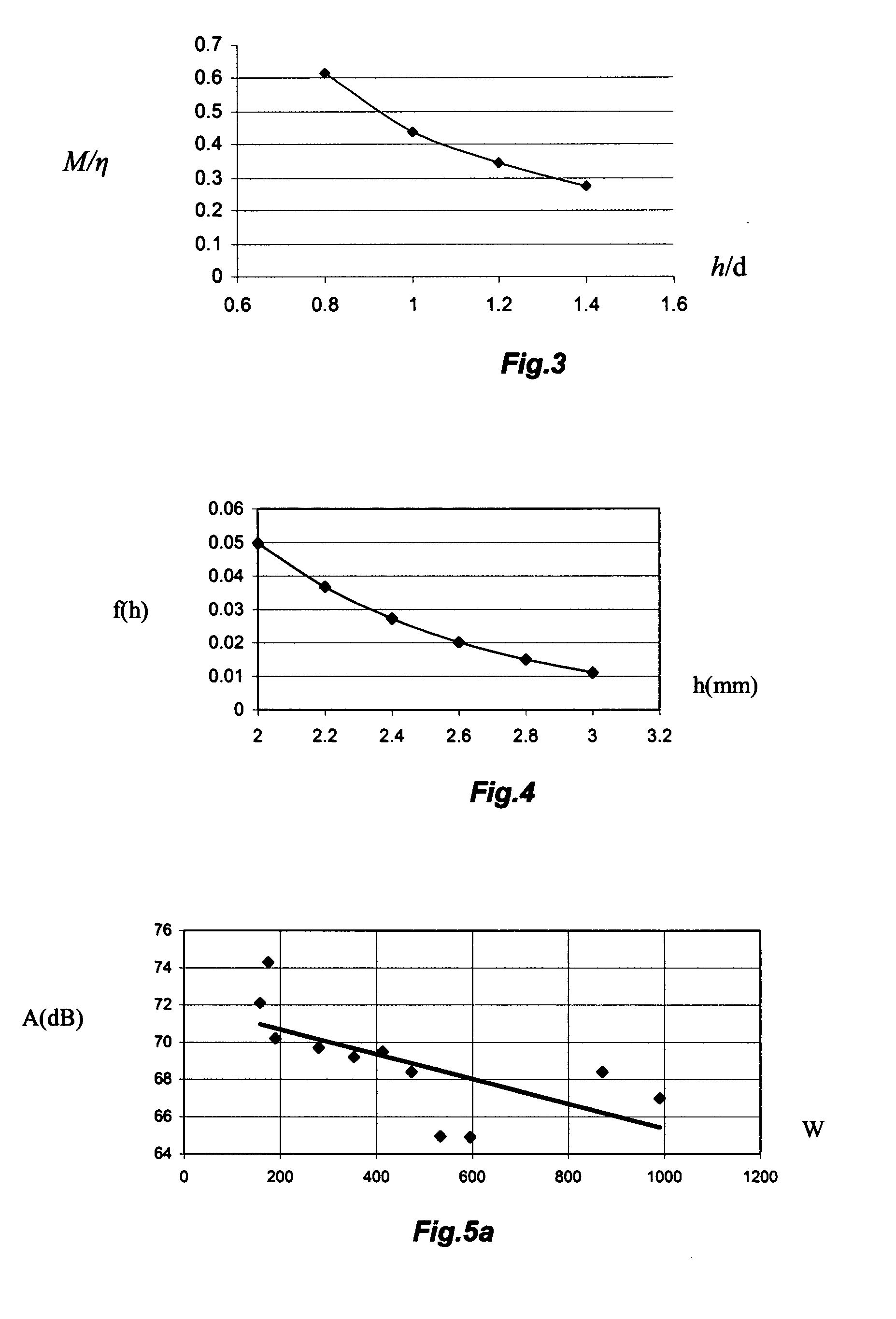
[0096] In the second example a calculation is shown of the relative mutual induction value M / η for the orientation system coils whose parameters are described in Example 1, when the coils are brought nearer or further relative to each other along axis y. The coils are arranged co-axially to each other, that is the value of the radial shift x=0. The change of M / η is calculated as a function of the relative clearance value between the nearest end faces of the coils hr=h / d, where d is the diameter of the coils. Formulas (2) were used for the calculations. The corresponding dependence is given in FIG. 3.

[0097] The graph in FIG. 3 shows that with the increase of the distance h between the end faces of the co-axially arranged coils of the orientation system the mutual induction value M decreases monotonously. Hence, by measuring the voltage on the sensing coil of the orientation system that is proportional to the mutual induction value of the exciting and the sensing coils, it is possibl...

example 3

[0098] This example shows the dependence calculation of the introduced eddy current probe inductance used for measuring the gap between its operating end face and the metallic foil surface of the battery body as a function of the gap, for example h2 in FIG. 1. An eddy current probe is used as a component part of the means for measuring the flat battery thickness between the arrays of the transmitting and the receiving ultrasonic probes.

[0099] It is known that the influence of the gap between the operating end face of the eddy current probe in the form of a short cylindrically shaped induction coil and the thin conducting plate on the value of the introduced impedance of the probe is described by an exponential cofactor [18]: Zad=48·10-7⁢ϖ⁢ ⁢RW2⁢ⅇ- ⁢3⁢hR⁢β2⁢th⁡(ς4⁢9+j·4⁢ ⁢β2)3⁢ ⁢9+j·4⁢ ⁢β2+(9+j·2⁢ ⁢β2)⁢th⁡(ς4⁢9+j⁢ ·4⁢β2),(3)

where Zad is the value of the introduced impedance of the eddy current probe, ω—frequency, R—probe radius, ω—number of windings, h=h2—gap value, β=R√ωσμ0, σ—sp...


PUM


Abstract

The present invention is an apparatus and method for determining the remaining service life of electrochemical energy generation and storage device including batteries, supercapacitors, DSSC solar cells and fuel cell. Measurements are performed by passing ultrasonic oscillations through the test object. The apparatus of the present invention comprises two arrays of transmitting and receiving ultrasonic probes between which the object being tested is affixed. Polyurethane tips are used for matching the acoustic resistance of the probes with the test object body. The apparatus includes means for positioning the transmitting and the receiving probe arrays relative to each other. The apparatus includes an electromagnetic means for measuring the test object thickness. The calibration characteristic for determining the remaining service life of a the test object are established from the signal values from the ultrasonic probes related to the number of charge-discharge cycles obtained at various charge values. A three-dimensional approximating dependence surface is constructed using the normalized signals from the receiving probes. The average value of this surface is determined. The remaining service life of the test object is determined using a calibration curve based on the average level of the surface

Description

REFERENCE TO RELATED APPLICATIONS [0001] Priority is claimed to co-pending U.S. Provisional Patent Application No. 60 / 835,650, filed Aug. 5, 2006.FEDERALLY SPONSORED RESEARCH [0002] None SEQUENCE LISTING [0003] None FIELD OF THE INVENTION [0004] The invention relates to the fields of electrical engineering, in particular to physical non-destructive testing of energy generating and storage devices, and especially to combined ultrasonic and electromagnetic testing of rechargeable and primary batteries, supercapacitors, solar cells and fuel cells to determine their service life. BACKGROUND OF THE INVENTION [0005] Among the achievements of present-day electrochemical engineering is the development and commercialization of an increasing variety of electrochemical energy generation and storage devices including high energy lithium-ion rechargeable batteries, high efficiency low cost dye sensitized solar cells (DSSC), and electric double layer capacitors (EDLC or supercapacitors). [0006] T...

Claims


Application Information

Patent Timeline
Patent Type & Authority Applications(United States)
IPC IPC(8): G01H1/00
CPCG01H1/16
Inventor REFKO, VOLODYMYRSHEMBEL, ELENAKHANDETSKYY, VOLODYMYR
Owner ENERIZE CORP
Why Eureka
Try Eureka