Pressurized fuel cylinder

a technology of pressure-driven fuel cylinders and pressure-controlled valves, which is applied in the direction of vessel construction details, transportation and packaging, transportation items, etc., can solve the problems of propane splashing into the vapor withdrawal pipe, pipe fatigue cracks, and significant stresses on the connection of the pipe to the service valve coupling, so as to reduce the possibility of liquid fuel splashing

Inactive Publication Date: 2008-02-07
MANCHESTER TANK & EQUIP
View PDF13 Cites 7 Cited by
  • Summary
  • Abstract
  • Description
  • Claims
  • Application Information

AI Technical Summary

Benefits of technology

[0007]It is an object of the present invention to provide a pressurized fuel cylinder for supplying fuel vapor to devices that may be operating in rough terrain and therefore be subjected to substantial jolts and vibrations.
[0009]It is yet another object of the present invention to provide a means for reducing the possibility of liquid fuel splashing into the vapor fuel withdrawal pipe inlet.
[0010]The present invention achieves these objectives by providing a fuel cylinder with a vapor fuel withdrawal pipe that is supported in one or more places by internal bracing and in which a liquid splash guard protects the inlet of the vapor fuel withdrawal pipe from splashing fuel.

Problems solved by technology

A significant problem exists in conventional gas cylinders with internal pipes for withdrawing liquid or gas, in that, due to the long lever arm presented by the pipe, vibrations of the pipe can result in significant stresses on the connection of the pipe to the service valve coupling.
As a result, the pipe can develop fatigue cracks at the point where it is internally threaded into the service valve coupling.
When horizontal propane tanks are used to fuel moving vehicles, such as lawnmowers, however, the tanks can be expected to operate in uneven or rough terrain in which sloshing and splashing of propane into the vapor withdrawal pipe could be a problem.
Further, the '996 patent does not address the need to protect the inlet of the vapor fuel pipe from splashing of liquid propane.

Method used


Image

  • Pressurized fuel cylinder
  • Pressurized fuel cylinder
  • Pressurized fuel cylinder

Examples


Embodiment Construction

[0020]The present invention and its advantages are best understood by referring to the drawings. The elements of the drawings are not necessarily to scale, emphasis instead being placed upon clearly illustrating the principles of the invention.

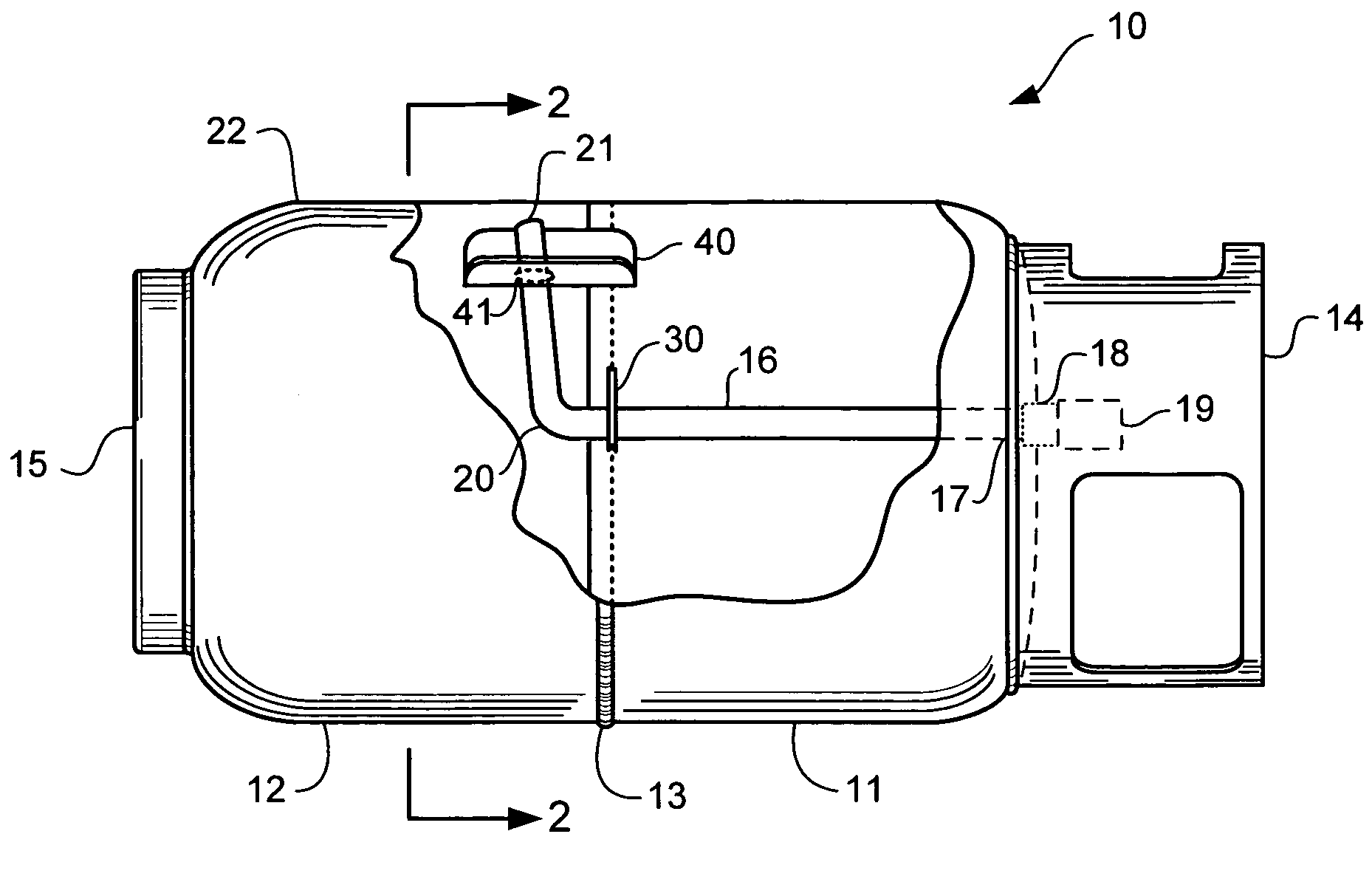
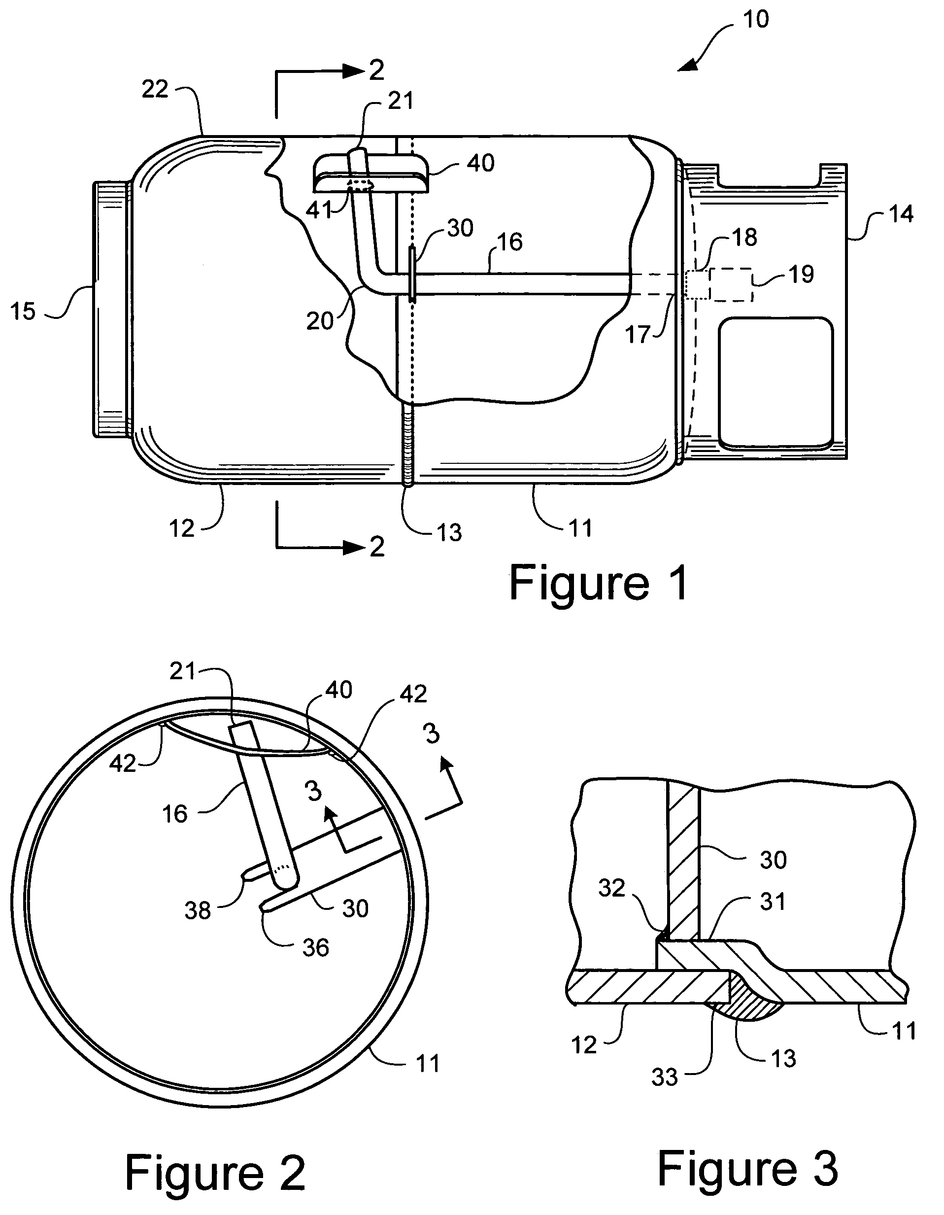
[0021]FIG. 1 illustrates one embodiment of a horizontal fuel gas cylinder 10 that may be used on a propane-powered lawnmower or other gas fuel-powered device. The cylinder 10 is made up of a “top” head section 11 and a “bottom” head section 12, which sections are secured together by a circumferential weld joint 13 to form a pressure vessel for containing fuel. (Note that the use of “top” and “bottom” head sections refers to the positioning of the cylinder in its traditional orientation, which is the orientation used for filling the cylinder, and not in its horizontal position, i.e., the position of its use.) Both the top head and the bottom head sections may be fabricated from aluminum or aluminum alloy to minimize the weight of the cylinder a...


PUM

PropertyMeasurementUnit
lengthaaaaaaaaaa
diameteraaaaaaaaaa
distanceaaaaaaaaaa

Abstract

A fuel cylinder for use in fueling vapor-powered machines and devices is claimed. The fuel cylinder contains a fuel vapor withdrawal pipe that bends upward towards the top edge of the cylinder when the cylinder is in its position of use, for example, the horizontal position if the tank is used horizontally. A liquid splash guard surrounds the inlet of the fuel vapor withdrawal pipe to protect the inlet from splashing of liquid propane in the cylinder. A brace connects to the fuel vapor withdrawal pipe to stabilize the fuel pipe during high vibration use. In one embodiment, the splash guard and brace are welded to the internal surface of a joggle in the rim of the upper head portion of the cylinder before the upper head portion and lower head portion of the cylinder are mated and welded together.

Description

FIELD OF THE INVENTION[0001]The present invention relates generally to the field of pressurized fuel cylinders, and more particularly to means for preventing splashing of liquid into the vapor withdrawal pipe and for stabilizing the pipe.BACKGROUND OF THE INVENTION[0002]Propane gas is becoming known as an attractive alternative to the use of conventional gasoline to fuel lawnmowers and other devices. Using propane tanks for lawnmowers eliminates the spillage associated with gasoline use and lessens harmful vapor releases. Propane versions of lawnmowers have been found to significantly reduce ozone-destroying emissions.[0003]Propane gas cylinders or tanks are generally made from lightweight metals such as aluminum, but may also be made of steel or composite material. Because the cylinders are typically laid on their sides when positioned on the lawnmower, a pipe, runs from the service valve coupling at the top of the cylinder into the interior of the cylinder, and has a bend formed i...

Claims


Application Information

Patent Timeline
Patent Type & Authority Applications(United States)
IPC IPC(8): B62D33/00
CPCF17C1/00F17C2201/0119F17C2201/032F17C2201/035F17C2201/058F17C2203/0617F17C2203/0639F17C2203/0646F17C2203/0648F17C2203/066F17C2205/018F17C2205/0323F17C2205/0332F17C2205/0352F17C2205/0394F17C2209/221F17C2209/227F17C2209/232F17C2221/035F17C2223/0153F17C2223/033F17C2223/045F17C2250/0413F17C2260/027F17C2270/07
Inventor SOMMER, JAMES G.LANE, ROBERT F.FREELAND, THOMAS B.
Owner MANCHESTER TANK & EQUIP
Why Eureka
Try Eureka