
Electrically controlled brake system

a brake system and electric control technology, applied in the direction of brake systems, vehicle position/course/altitude control, instruments, etc., can solve the problems of increasing the cost of the brake system, increasing the cost, and imposing a considerable space in the cab of the operator's cab, so as to increase the braking force and the braking pressure. , to achieve the effect of increasing the braking force of the anti-jackknifing brak

Active Publication Date: 2008-02-07
WABCO GMBH
View PDF13 Cites 31 Cited by
  • Summary
  • Abstract
  • Description
  • Claims
  • Application Information

AI Technical Summary

Benefits of technology

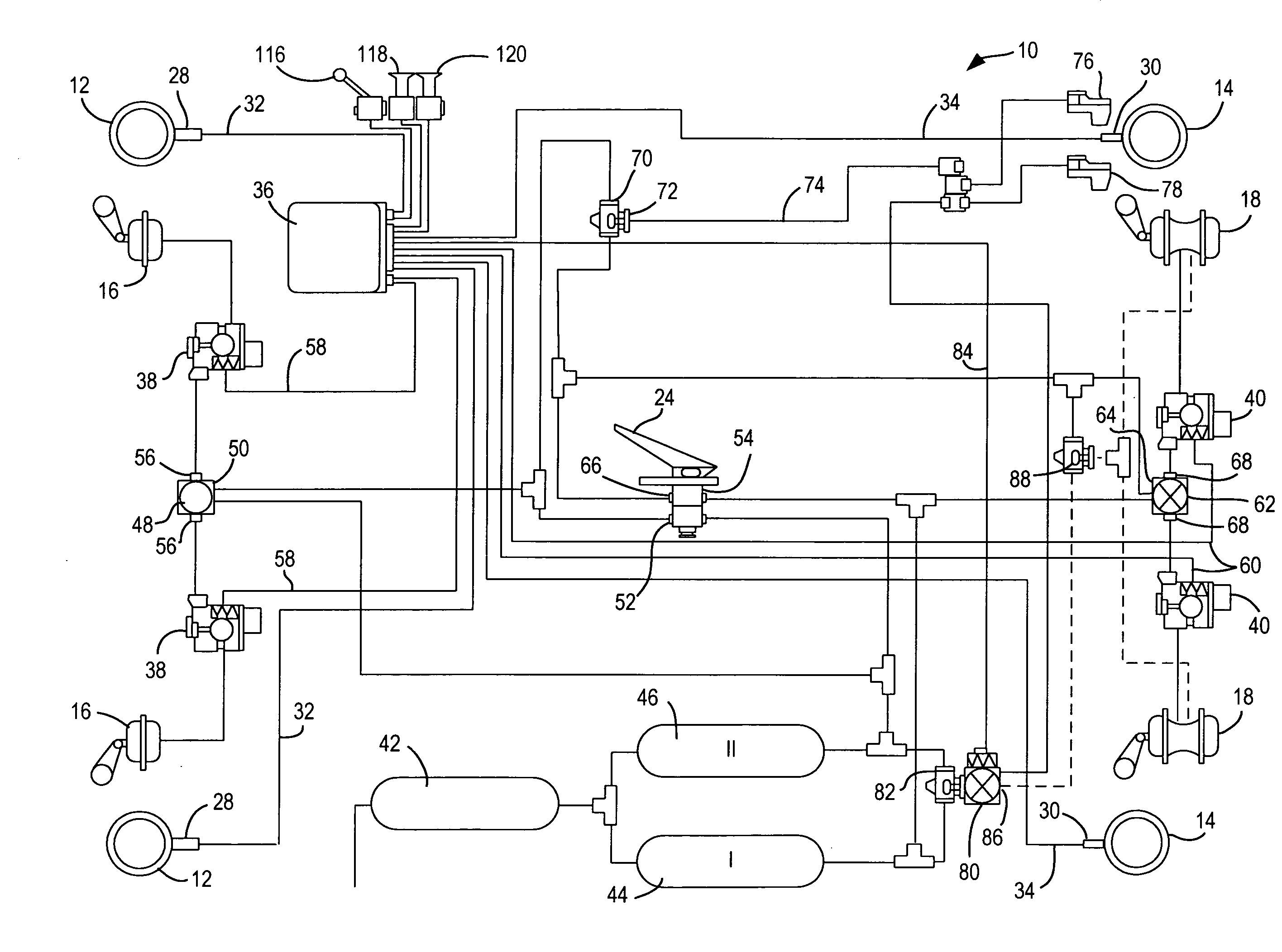
[0006]By the use of an electrical operating element to control the anti-jackknifing brake, the installation of compressed-air lines in the operator's cab can be avoided. It is necessary only to route electrical lines, which are substantially more flexible, more space-saving and less expensive. The electrical operating element can be disposed in the operator's cab such that it can be manually operated without difficulty by the operator, and be independent of the foot brake pedal by means of which the service brake of the vehicle is actuated.
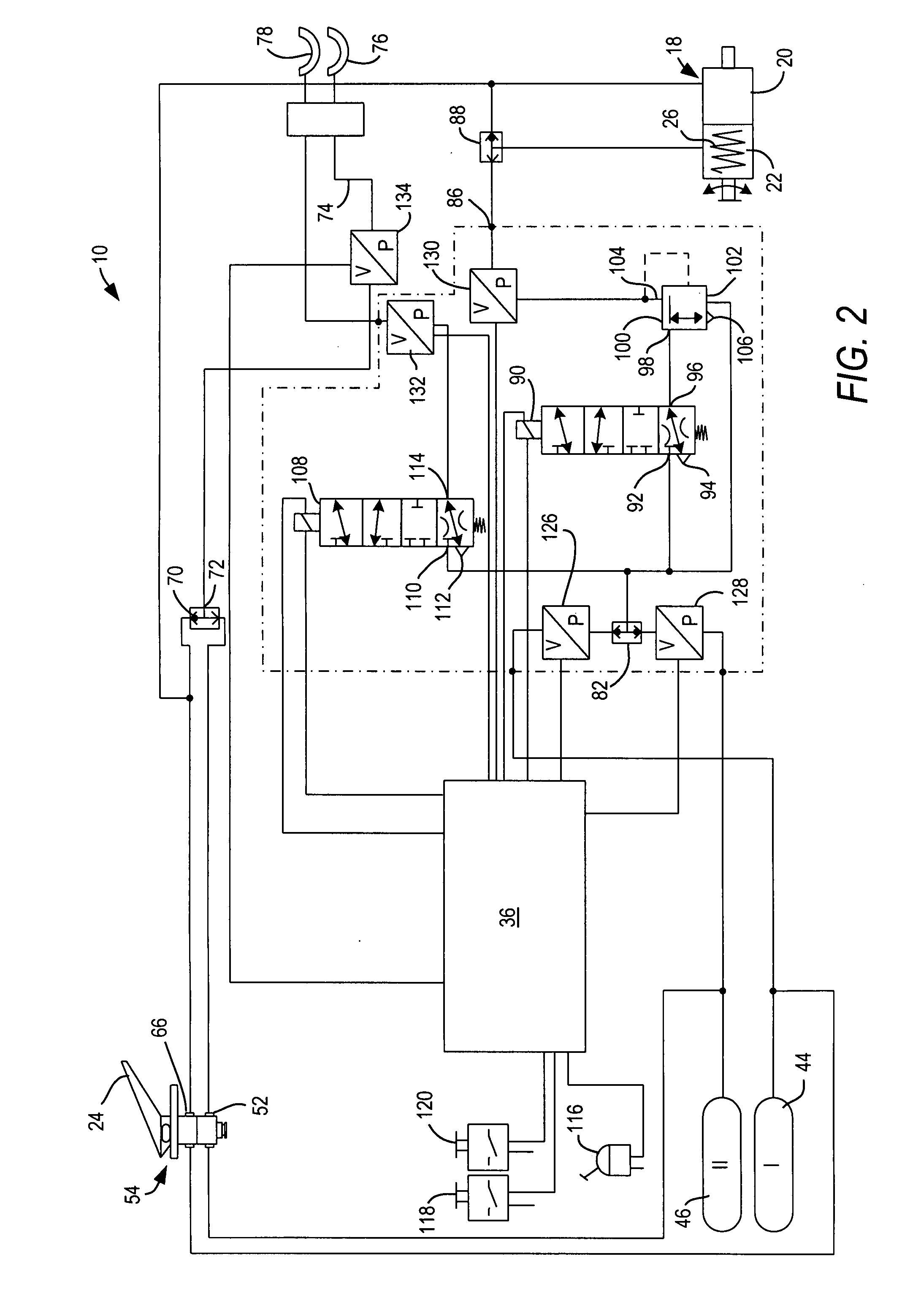
[0017]According to still another embodiment of the present invention, the control device for control of the valve device for increasing the braking force of the anti-jackknifing brake is integrated into an anti-lock brake system control unit of the tractor. Alternatively, this control device is integrated in a separate control unit for the parking brake. In both cases, use of existing control units can be made so that no further control units have to be installed for the anti-jackknifing brake. Thus, additional installation expense can be avoided or minimized.

Problems solved by technology

This is a disadvantage since compressed-air lines must be installed in the operator's cab, which therefore makes the brake system more expensive.
Also, more stringent safety requirements must be satisfied when compressed-air lines are routed in an operator's cab, also contributing to the greater cost.
Furthermore, the routing of compressed-air lines in an operator's cab imposes a considerable demand for space in the cab, at the expense of the operator's comfort.

Method used


Image

  • Electrically controlled brake system
  • Electrically controlled brake system
  • Electrically controlled brake system

Examples


Embodiment Construction

[0038]As used herein, the term “trailer” is to be understood as any mobile unit that can be towed by a tractor; in particular, the term “trailer” includes vehicles resting on a plurality of axles, as well as vehicles constructed on only one axle or on one double axle and supported at one of their ends on the tractor (such vehicles are also known as “semitrailers”).

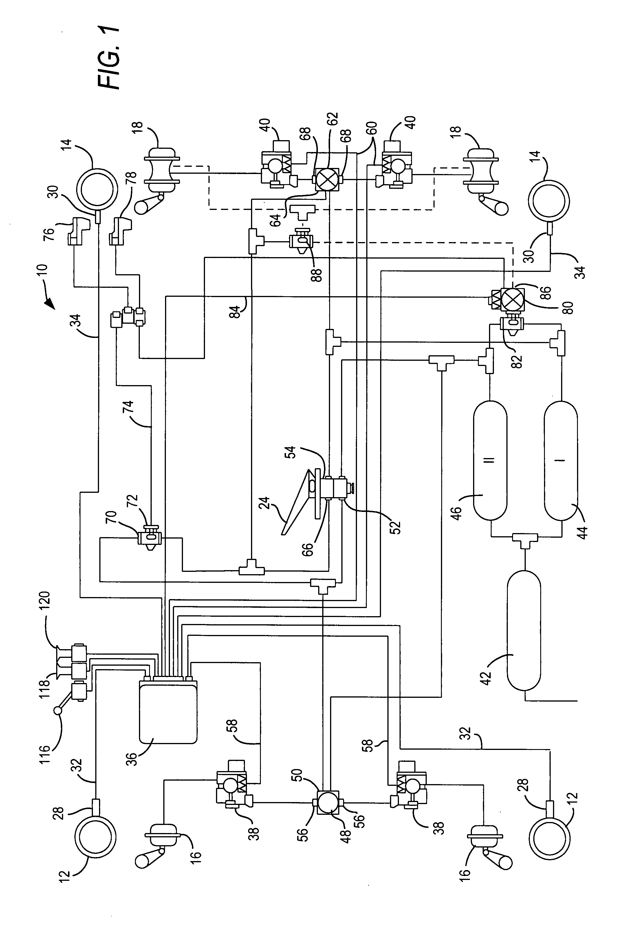
[0039]Referring now to the drawing figures where like reference numerals are used for corresponding parts, FIGS. 1 and 2 depict an air-brake system 10 for a vehicle, such as, for example, a commercial vehicle (e.g., truck or bus), that can be operated with a trailer. In FIG. 1, two wheels 12 of a front axle and two wheels 14 of a rear axle are shown. Wheels 12 of the front axle are braked via brake cylinders 16, and wheels 14 of the rear axle are braked via brake cylinders 18.

[0040]It should be understood that, even if only four wheels on two axles are represented, the present invention is not limited to such a number of w...


PUM


Abstract

An electrically controlled brake system 10 for a tractor is provided that is equipped with an anti-jackknifing brake that can be actuated by means of a manual operating element and that acts only on the brakes of a trailer coupled to the tractor. The operating element is an electrical element which generates an electrical signal to control a valve device by means of which the braking force of the anti-jackknifing brake can be increased.

Description

BACKGROUND OF THE INVENTION[0001]The present invention is directed generally to a new electrically controlled brake system for a tractor, the system including a manually actuatable anti-jackknifing brake that acts only on the brakes of a trailer connected to the tractor.[0002]Brake systems with anti-jackknifing brakes are known. Anti-jackknifing brakes are used, for example, to maintain appropriate spacing on downhill grades between the tractor and the trailer in a vehicle train. Such anti-jackknifing brakes are also used advantageously on level driving surfaces. Further, anti-jackknifing brakes are useful for testing the braking effect of the trailer. Further still, the connection of the tractor to the trailer can also be tested with anti-jackknifing brakes.[0003]In conventional brake systems with anti-jackknifing brakes, the service brake of the trailer is actuated via a manual lever in the vehicle operator's cab in order to brake only the trailer (the tractor is not braked during...

Claims


Application Information

Patent Timeline
IPC IPC(8): B60T13/68
CPCB60T8/327B60T7/20B60T13/04B60T13/588B60T13/683B60T7/08B60T8/1708B60T13/66
Inventor BENSCH, UWEFORSTER, HENNINGHELMER, JORGKIEL, BERND-JOACHIMROSENDAHL, HARTMUTSTRUWE, OTMARTIEDTKE, MATTHIAS
Owner WABCO GMBH
Learn More