
Electronic article surveillance marker

a technology of electronic articles and markers, applied in the direction of burglar alarms, mechanical actuation of burglar alarms, instruments, etc., can solve the problems of stray magnetic fields, difficult to manufacture markers that cannot be detected by the surveillance system, and add frequency instability to stray magnetic fields, so as to improve frequency stability and enhance deactivation and magnetic stability

Inactive Publication Date: 2008-02-07
TCI LTD
View PDF19 Cites 7 Cited by
  • Summary
  • Abstract
  • Description
  • Claims
  • Application Information

AI Technical Summary

Benefits of technology

[0014]The present invention provides a shallow cavity magnetomechanical electronic article surveillance marker that can be produced using as cast, i.e., unannealed, resonator material biased at the minimum point of the bias-frequency curve. The magnetomechanical marker has enhanced deactivation and magnetic stability since the marker is biased at the frequency minimum. The resonator material can be slit after casting. Applicant has found that combining the described unannealed, nonlinear resonator material and described abrupt low energy bias in the dual resonator configuration of the present invention, the weight and shape of the first resonator mechanically interfere with the second resonator to impart a stress on the second resonator, which shifts the frequency minimum of the marker to the bias point, thereby providing maximum frequency shift when the marker is deactivated and improved frequency stability. The present invention also provides maximum marker signal at the bias point.

Problems solved by technology

This change in the resonant frequency can cause the markers to be outside the predetermined frequency detection range of the electronic article surveillance system resulting in markers that may not be detected by the surveillance system.
The linear resonator configuration taught by U.S. Pat. No. 5,469,140 offers acceptable signal amplitude response in the interrogation zone of an electronic article surveillance system; however, it is difficult to manufacture this marker to match the industry standard interrogation frequency of 58 kHz.
The manufacturing difficulties are due to the fact that the frequency minimum occurs at a very high bias field level.
This high slope adds frequency instability to stray magnetic fields.
It is neither practical nor economical to produce a flat label product with a strong magnet which imparts a 10 oersteds field due to the high magnetic force of attraction which causes amplitude energy losses due to friction.
Magnets with this amount of bias field strength also cause excess amplitude losses due to friction.
Herzer also teaches that prior art resonator strips that have been optimized for multiple resonator labels have proven to be unsuitable for single resonator labels and vice versa.
However, the bias magnet must not be overly sensitive to stray magnetic fields that may affect the frequency response of the marker, thereby rendering it undetectable by the surveillance system.
; nevertheless, none of the solutions have totally satisfied the marketplace.

Method used


Image

  • Electronic article surveillance marker
  • Electronic article surveillance marker
  • Electronic article surveillance marker

Examples


Embodiment Construction

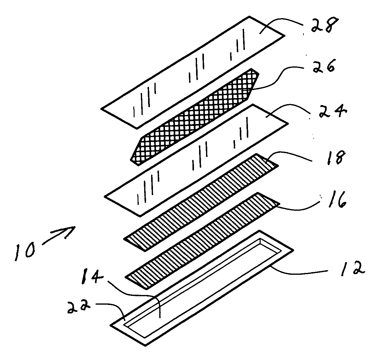
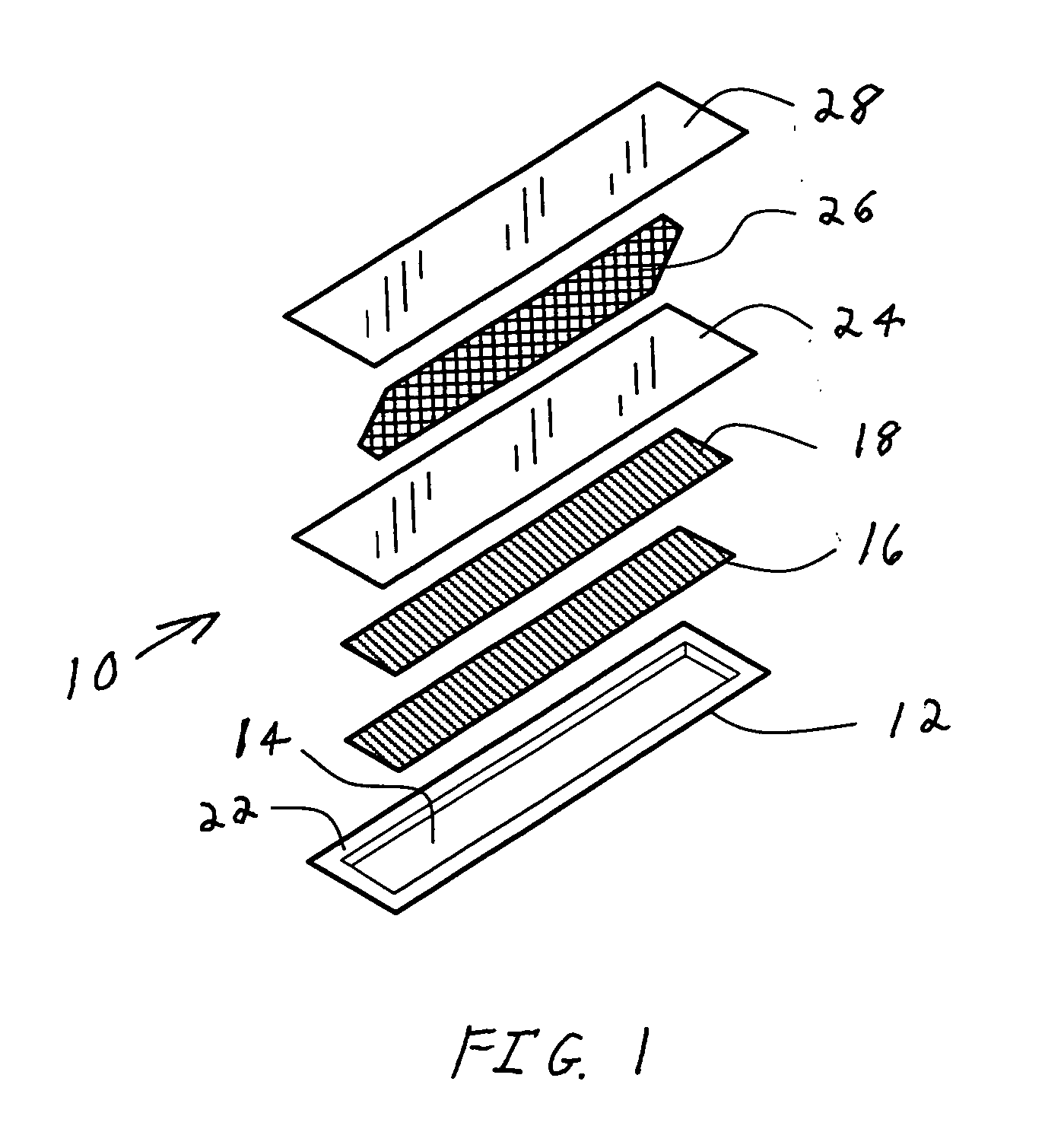
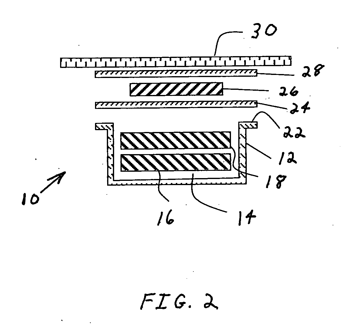
[0024]Referring to FIGS. 1-3, a marker 10 for use in an electronic article surveillance system has a housing 12 composed of sheet-form plastic material in which an indentation or cavity 14 is formed. Housing 12 has the shape of a rectangular prism and is open on one of its large faces. Cavity 14 is sized to accommodate a magnetomechanical element, such as two resonator strips 16 and 18 placed therein in stacked registration. Resonator strips 16 and 18 can have a width, for example of 6 mm. Optionally, small projections 20 are molded into the long sides and / or ends of cavity 14. Projections 20 facilitate centering resonator strips 16 and 18 in cavity 14 without unduly constraining them mechanically. Housing 12 has lips 22 surrounding cavity 14 on all four sides. The depth of cavity 14 is defined generally by the spacing between the plane of the bottom of the cavity 14 and the parallel plane of the surfaces of lips 22. A layer of flat polymer sheet or lidstock 24 is placed over cavity...


PUM


Abstract

A magnetomechanical marker for use in an electronic article surveillance system comprising a magnetomechanical element, a bias magnet and a housing. The magnetomechanical element comprises first and second resonator strips composed of an unannealed magnetostrictive amorphous metal alloy having a resonant frequency response including a resonant frequency minimum in response to the incidence thereon of an electromagnetic interrogating field. The bias magnet has a bias point to magnetically bias the magnetomechanical element so that the magnetomechanical element resonates at a predetermined frequency in the presence of an electromagnetic interrogating field. The housing has a cavity sized and shaped to accommodate the first and second resonator strips positioned in the cavity in registration and to allow the first and second resonator strips to mechanically vibrate, wherein the first resonator strip has a first weight and first shape and is positioned proximate the second resonator strip so that the first weight and the first shape mechanically interfere with the second resonator strip to impart a stress on the second resonator strip which shifts the resonant frequency minimum to the bias point.

Description

CROSS-REFERENCE TO RELATED APPLICATION[0001]N / ASTATEMENT REGARDING FEDERALLY SPONSORED RESEARCH OR DEVELOPMENT[0002]N / ABACKGROUND OF THE INVENTION[0003]This invention relates to electronic article surveillance systems and, more particularly, to a magnetomechanically resonant marker for use in article surveillance systems.[0004]Attempts to protect articles of merchandise and the like against theft from retail stores have resulted in numerous technical arrangements, often termed electronic article surveillance. Many of the forms of protection employ a tag or marker secured to articles for which protection is sought. The marker responds to an electromagnetic interrogation signal from a transmitting antenna situated proximate either an exit door of the premises to be protected, or an aisle adjacent to the cashier or checkout station. A nearby receiving antenna receives a signal produced by the marker in response to the interrogation signal. The presence of the response signal indicates ...

Claims


Application Information

Patent Timeline
Patent Type & Authority Applications(United States)
IPC IPC(8): G08B13/14
CPCG08B13/2408G08B13/2442G08B13/2437G08B13/2422
Inventor GADONNIEX, DENNIS M.HANSEN, NORMAN
Owner TCI LTD
Learn More