Process and apparatus for producing a mixed feed stream for a steam reforming plant

a technology of steam reforming plant and feed stream, which is applied in the direction of chemistry apparatus and processes, gaseous mixture working up, refining to eliminate heteroatoms, etc., can solve the problems of reducing the temperature of the reactor too much, affecting pre-reform, and reducing the logistics needed for steam and oxygen supply, so as to avoid undesired cracking and polymerization reactions, the effect of increasing the decomposition of unsaturated

Active Publication Date: 2019-03-14
LAIR LIQUIDE SA POUR LETUDE & LEXPLOITATION DES PROCEDES GEORGES CLAUDE
View PDF4 Cites 0 Cited by
  • Summary
  • Abstract
  • Description
  • Claims
  • Application Information

AI Technical Summary

Benefits of technology

[0034]According to the invention, the required hydrogenation of the mono- and diolefins and the hydrodesulfurization of the organic sulfur compounds contained in the feed stream are carried out step by step under process conditions optimized in each case. Furthermore, the inlet temperature into the respective reaction zone is controlled such that overheating of the feedstocks is avoided, which otherwise leads to undesired coke deposits, cloggings and the accelerated deactivation of the catalysts used.
[0064]In a further aspect of the apparatus according to the invention the first heating device is designed as heat exchanger and suited to carry out an indirect heat exchange between the first feed stream and a hot raw synthesis gas product stream from the steam reforming plant, a hot flue gas stream from the reformer furnace, or a hot product gas stream from the CO conversion plant (CO shift) downstream of the steam reforming plant. Due to this configuration the heat content of said process streams is utilized for heating the first feed stream and thus the energy efficiency of the entire process is improved.

Problems solved by technology

What is disadvantageous is the logistics needed for supplying steam and oxygen.
Too much addition of steam also can lower the temperature in the reactor too much and thus negatively influence pre-reforming.
Furthermore, the downstream sulfur separation then is impaired as well.
It is very disadvantageous that all pretreatment devices accordingly must be present twice.

Method used


Image

  • Process and apparatus for producing a mixed feed stream for a steam reforming plant
  • Process and apparatus for producing a mixed feed stream for a steam reforming plant
  • Process and apparatus for producing a mixed feed stream for a steam reforming plant

Examples


numerical examples

[0089]In the following numerical examples the mode of action of the invention is illustrated with reference to the results of simulation calculations. Organic sulfur components are not taken into account here, as for the resulting temperature profiles the hydrogenation of the mono- and diolefins is decisive.

[0090]Both examples are based on natural gas as first feed stream and on a refinery waste gas as second feed stream. The compositions of the first and the second feed stream are shown in the columns for conduit 10 and conduit 24 of the material stream table indicated below. All further indications in the material stream table only are applicable for Example 2. The hydrogen content of the refinery waste gas is sufficient for the hydrogenation steps according to the invention, so that the recirculation of hydrogen from the hydrogen product stream of the steam reforming plant can be omitted.

example 1

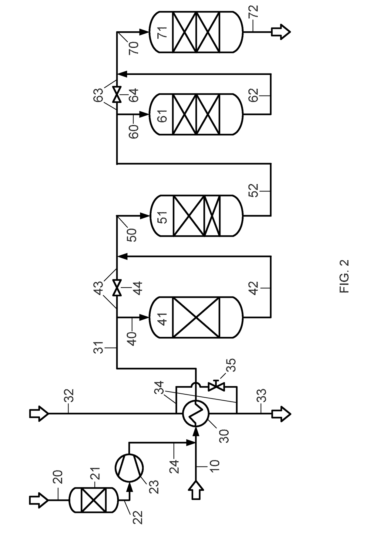
[0091]According to the first aspect of the invention natural gas as first feed stream is guided to the heat exchanger 30 via conduit 10 at room temperature (25° C.). A refinery waste gas as second feed stream initially is demetallized in the adsorber 21 and subsequently condensed in the condenser 23 and then has a temperature of 81° C. Via conduit 24 the second feed stream is combined with the first feed stream. In the heat exchanger 30 the mixed feed streams are heated such that the temperature in conduit 40 is 260° C. before entry into the diolefin hydrogenation reactor 41. Due to the exothermally proceeding hydrogenation of the diolefins and a part of the olefins, the temperature in conduit 50 before entry into the second hydrogenation stage (reactor 51, olefin hydrogenation+HDS) is about 290° C. Due to the again released reaction enthalpy of the hydrogenation of the olefins and sulfur compounds the temperature at the outlet of the reactor 51 is about 360° C. (conduit 52). With a...

example 2

[0093]The composition and properties of important material streams in conjunction with the following explanation of a second example are shown in the indicated material stream table.

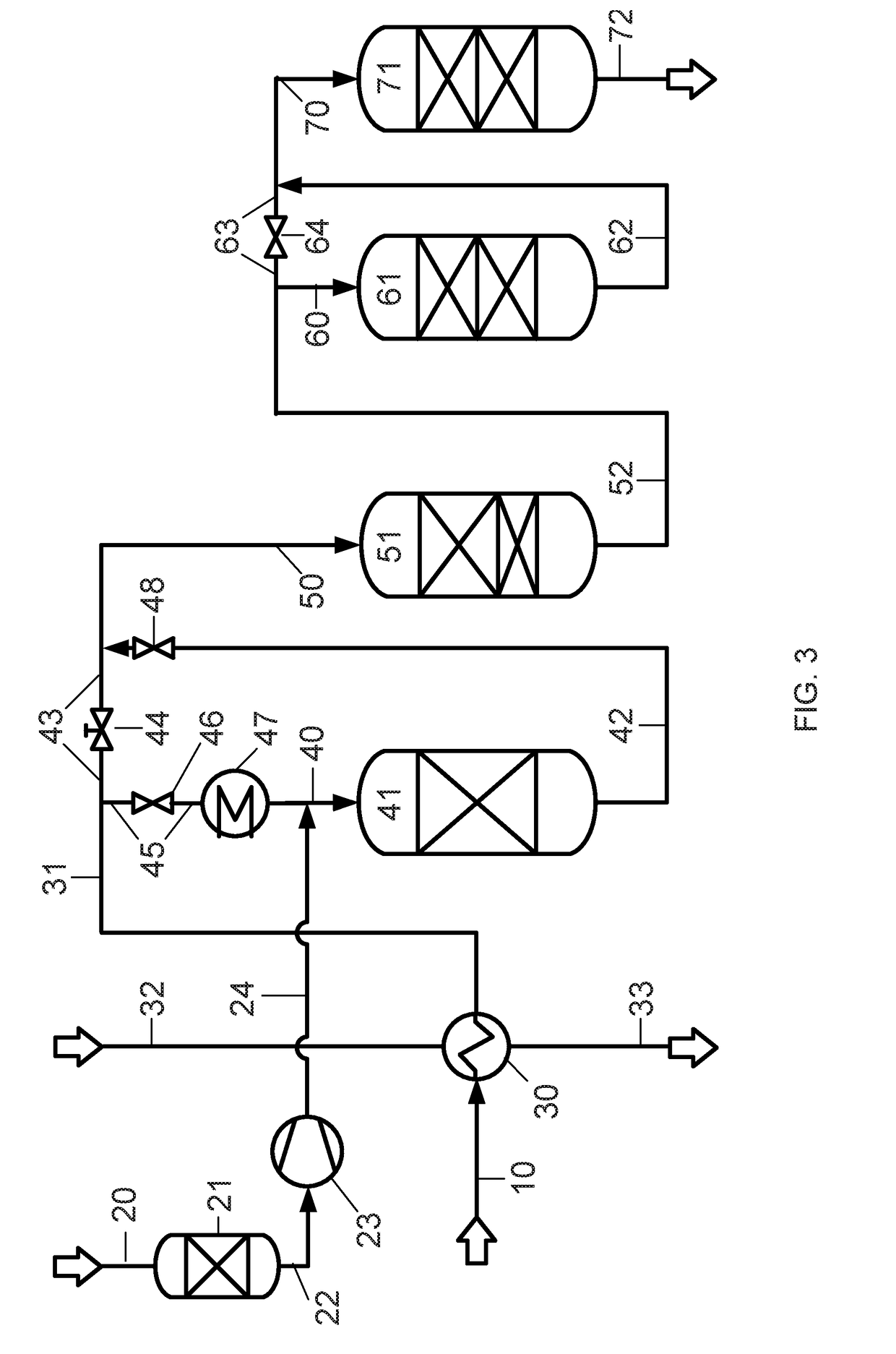
[0094]According to the second aspect of the invention natural gas as first feed stream is guided to the heat exchanger 30 via conduit 10 at room temperature (25° C.). In the heat exchanger 30 the natural gas stream is heated without admixing the second feed stream, so that the gas temperature in conduit 31 before branching into conduits 43 and 45 is 368° C. The first hydrogenation partial stream branched off via conduit 45 is introduced into the cooling device 47, cooled there. and via conduit 40 combined with the second feed stream, which is supplied via conduit 24 and has a temperature of 81° C. The mixture obtained then enters into the diolefin hydrogenation reactor 41 with a temperature of 222° C. and leaves said reactor in conduit 42 with a temperature of 229° C. After combining and mixing with the ...


PUM

PropertyMeasurementUnit
temperatureaaaaaaaaaa
temperaturesaaaaaaaaaa

Abstract

This invention relates to a process and an apparatus for producing a mixed feed stream for a steam reforming plant from a first feed stream containing methane and a second feed stream comprising higher hydrocarbons, olefins and diolefins. According to the invention, the required hydrogenation of the mono- and diolefins and the hydrodesulfurization of the organic sulfur compounds contained in the feed stream are carried out step by step under process conditions optimized in each case. Furthermore, the inlet temperature into the respective reaction zone is controlled such that overheating of the feedstocks is avoided, which otherwise leads to undesired coke deposits, cloggings and the accelerated deactivation of the catalysts used.

Description

CROSS REFERENCE TO RELATED APPLICATIONS[0001]This application is a § 371 of International PCT Application PCT / EP2017 / 025037, filed Mar. 6, 2017, which claims the benefit of EP16400005.1, filed Mar. 16, 2016, both of which are herein incorporated by reference in their entireties.FIELD OF THE INVENTION[0002]The present invention relates to a process for producing a mixed feed stream for a steam reforming plant which contains at least one reforming stage. The mixed feed stream comprises a first feed stream containing methane and a second feed stream comprising higher hydrocarbons, olefins and diolefins, wherein the first and / or the second feed stream also contains organic sulfur compounds. As first feed stream natural gas can be used, and as second feed stream for example a refinery waste gas. The second feed stream also can contain methane, hydrogen as well as metals and chlorides.[0003]Furthermore, the invention also relates to an apparatus for carrying out such process.BACKGROUND[00...

Claims


Application Information

Patent Timeline
Patent Type & Authority Applications(United States)
IPC IPC(8): C01B3/38C10G25/00C10G45/02C10G45/32C10G67/06C10G70/02C10G70/04
CPCC01B3/38C10G25/00C10G45/02C10G45/32C10G67/06C10G70/02C10G70/046C01B2203/0233C01B2203/127C01B2203/0227C01B2203/1264C10G45/00C01B2203/1241
Inventor OTT, JORGLEHMANN, MAIKNIEDING, SEBASTIANSZIELEIT, CHRISTIAN
Owner LAIR LIQUIDE SA POUR LETUDE & LEXPLOITATION DES PROCEDES GEORGES CLAUDE
Why Eureka
Try Eureka