
System and method for tracking medical device using magnetic resonance detection

a magnetic resonance detection and medical device technology, applied in the field of system and method for tracking medical devices using magnetic resonance detection, can solve the problems of significant interference with the main signal, less accurate tracking devices, and significant interference with the rf coil, and achieve the effect of reducing interference in the response signal

Inactive Publication Date: 2008-02-07
INSIGHTEC
View PDF9 Cites 86 Cited by
  • Summary
  • Abstract
  • Description
  • Claims
  • Application Information

AI Technical Summary

Benefits of technology

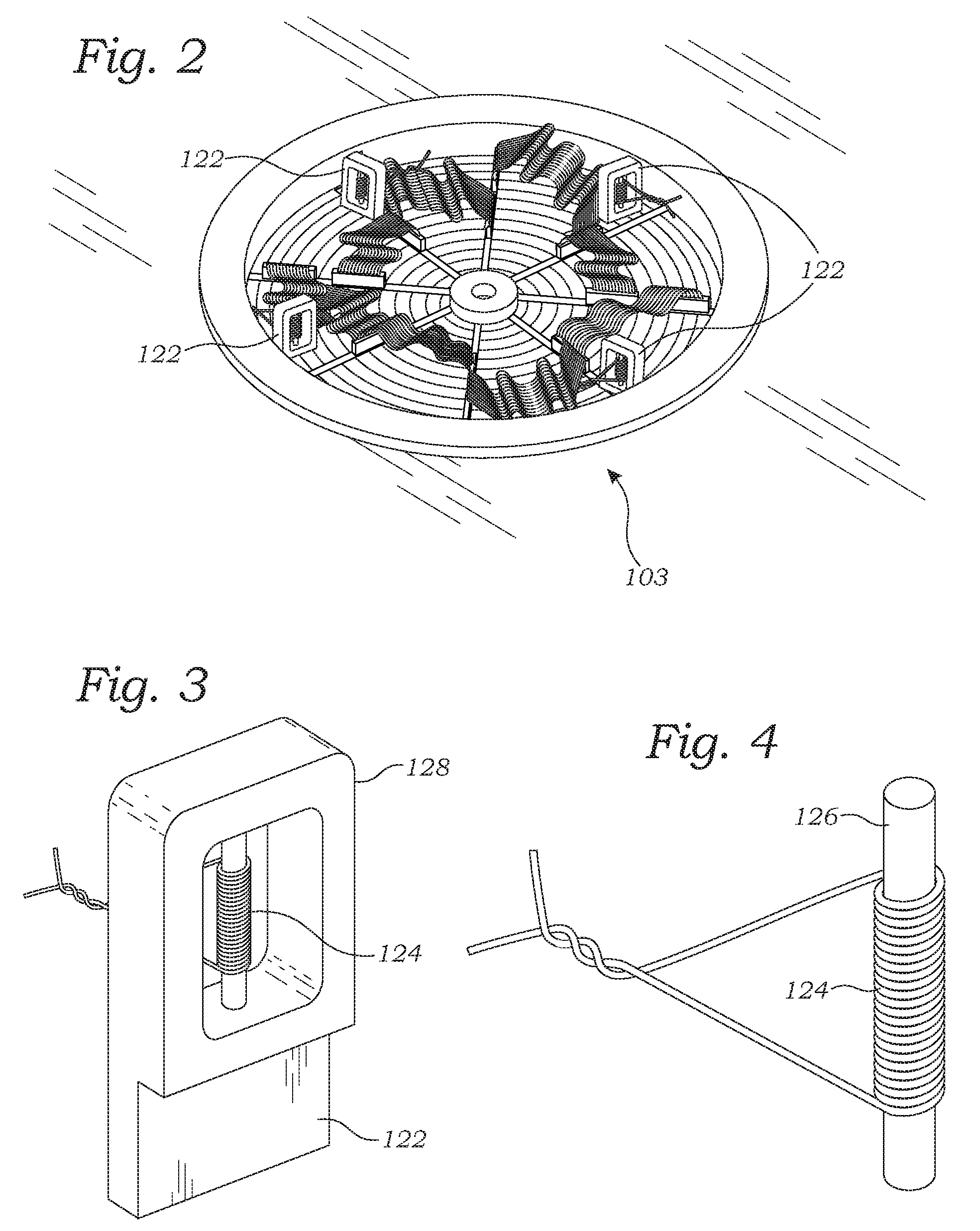
[0010]In accordance with the present invention, a system and method is described for using MR to track a medical device which reduces the interference signal suffered by prior systems. The system comprises an MR tracking device(s) which may comprise RF tracking coil or other suitable receiving component which can receive an MR response signal emitted by material excited by an MR machine. The RF tracking coil may comprise a conductive wire formed into a helical coil. A small tube filled with MR sensitive material like water or oil may be inserted into the winding of the RF tracking coil. The MR tracking device(s) may be attached to any medical device such as an ultrasonic or radiation ablation device, a catheter or other instrument.
[0011]In one innovative aspect of the present invention, an improved pulse sequence for the magnetic field gradient is utilized to attenuate the interfering signal suffered by prior systems. The interfering signal is primarily produced by a wide spread, large volume of MR sensitive material outside the close vicinity of the RF tracking coil. Therefore, the interfering signal, has a very wide bandwidth, and short echo duration. In comparison, the MR response signal emanates from the small volume in the vicinity of the RF tracking coil has a very low bandwidth and long echo duration.
[0013]It thus is an object of the invention to provide a system and method for an MR tracking device which has reduces interference in the response signal.

Problems solved by technology

However, in practice, there may be significant interference received by the RF coil.
This signal represents interference which makes the tracking device less accurate because it is emitted by material that is not in close vicinity to the RF tracking coil.
Moreover, although the coupling may be relatively weak, the signal can cause significant interference with the main signal because the interfering signal emanates from a volume of material that is many orders of magnitude larger than the primary signal emitted by the sensitive volume in close vicinity to the RF tracking coil.

Method used


Image

  • System and method for tracking medical device using magnetic resonance detection
  • System and method for tracking medical device using magnetic resonance detection
  • System and method for tracking medical device using magnetic resonance detection

Examples


Embodiment Construction

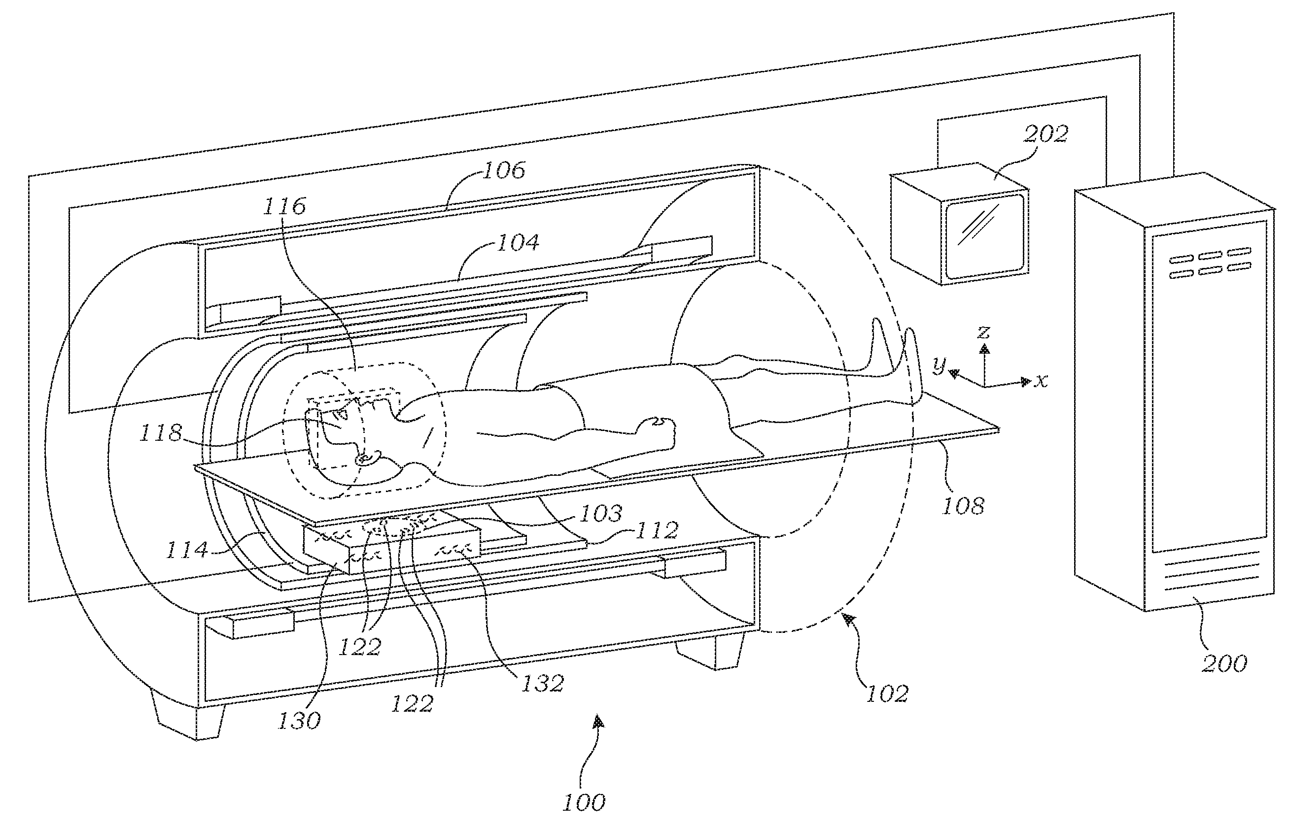
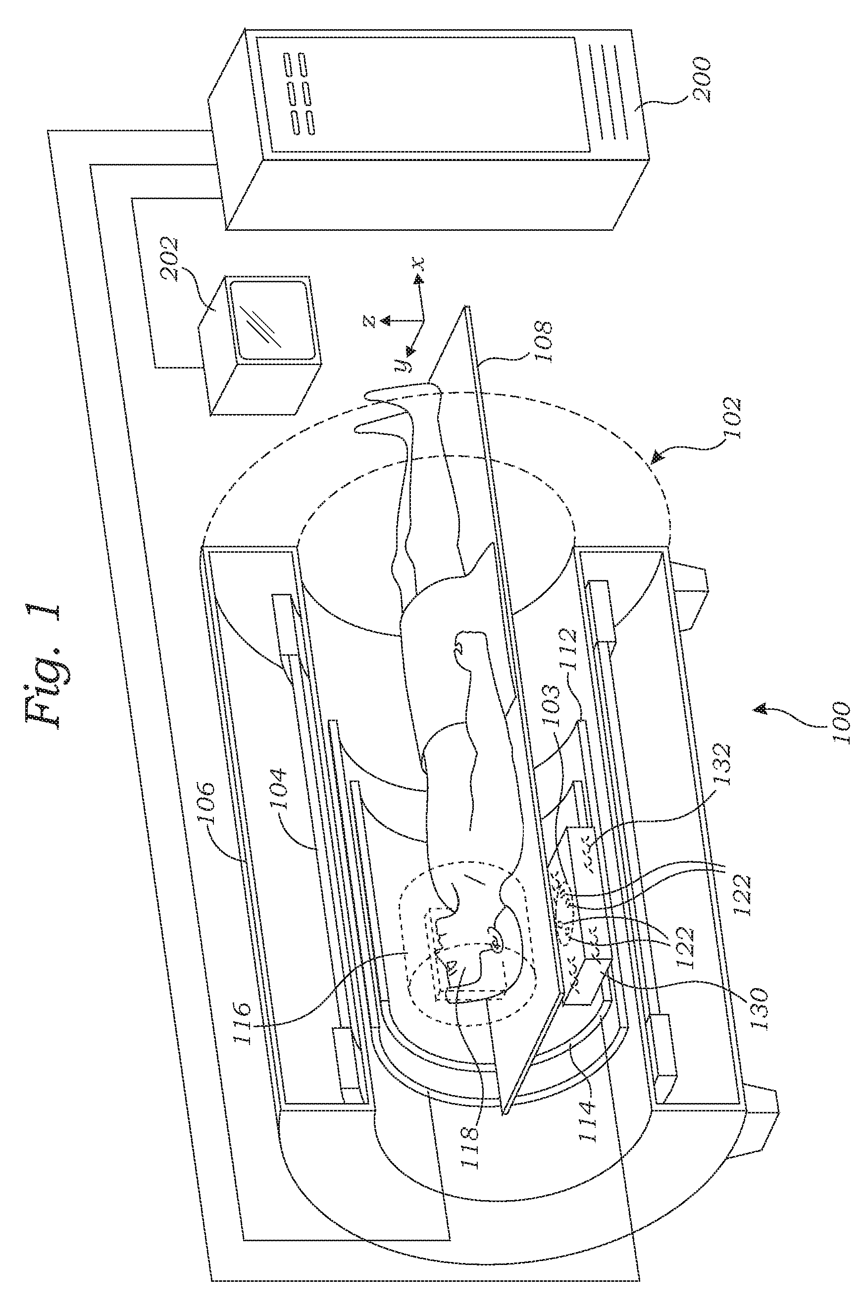
[0021]As shown in FIG. 1 the MRI system 100 according to the present invention comprises an MRI machine 102, and a medical device 103 disposed within the bore of the MRI machine 102. The components and operation of the MRI machine are known in the art so only some basic components helpful in the understanding of the system 100 and its operation will be described herein.

[0022]The MRI machine 102 typically comprises a cylindrical electromagnet 104 which generates a static magnetic field within the bore 105 of the electromagnet 104. The electromagnet 104 generates a substantially homogeneous magnetic field within the imaging region 116 inside the magnet bore 105. The electromagnet 104 may be housed in a magnet housing 106. A support table 108 is disposed within the bore 105 of the magnet, upon which a patient 110 is placed. The patient is located with the volume of interest 118 within the patient 110 placed within the imaging region 116 of the MRI machine 102.

[0023]A set of cylindrical...


PUM


Abstract

A system and method for using magnetic resonance to track a medical device which attenuates interfering MR signals. The system comprises an MR tracking device comprising one or more radiofrequency (RF) tracking coils adapted to receive a magnetic resonance MR response signal from nuclei excited by an RF pulse. Ideally, the RF tracking coil only receives an MR response signal from nuclei in matter in the close vicinity of the tracking device. The tracking device is attached to medical device. The interfering signal tends to emanate from large objects or large volumes that are outside the close vicinity of the tracking device but which are still weakly coupled to the tracking device. A dephasing gradient is applied perpendicular to the readout gradient before the RF response signal is received thereby dephasing the interfering signal emanating from remote nuclei, which strongly attenuates the interfering signal while the MR response signal is substantially unaffected. The system can also detect errors in tracking location by checking the amplitude of the signal from each coil and the detected distance between each coil, and correcting for such errors by ignoring data from coils having low amplitude or location deviating from known location relative to the other coils.

Description

RELATED APPLICATION DATA[0001]This application claims the benefit under 35 U.S.C. 119 to U.S. Provisional Application No. 60 / 821,121, filed on Aug. 1, 2006, the contents of which are incorporated herein by reference.FIELD OF THE INVENTION[0002]The field of the invention generally relates to systems and methods for monitoring the position of medical devices attached or inserted into a body during a medical procedure, and more particularly to tracking such medical devices using magnetic resonance imaging.BACKGROUND OF THE INVENTION[0003]Magnetic resonance (MR) imaging of internal human tissue of the body and also MR tracking of devices inserted into the body is known by those of skill in the art, and therefore, need not be described in detail herein. Such MR imaging may be used for numerous medical procedures, including diagnosis, surgery, non-invasive surgery, minimally invasive surgery, and the like. In general terms, the method of imaging using MR consists of subjecting the subject...

Claims


Application Information

Patent Timeline
IPC IPC(8): A61B5/055
CPCA61B5/055A61B5/06G01R33/4814G01R33/287A61B2019/5458A61B2090/3958
Inventor ASSIF, BENNY
Owner INSIGHTEC
Learn More