Robotically controlled catheter and method of its calibration

a robotic control and catheter technology, applied in the field of robotic control devices, can solve the problems of inability to accurately predict the relative changes desired in the tip position, the inherent error of extant positional feedback systems such as the navigation system described above, and the inability to accurately characterization the catheter open loop

Active Publication Date: 2008-02-07
ST JUDE MEDICAL ATRIAL FIBRILLATION DIV
View PDF99 Cites 44 Cited by
  • Summary
  • Abstract
  • Description
  • Claims
  • Application Information

AI Technical Summary

Benefits of technology

[0019] A technical advantage of the present invention is that it accounts for device variability error, positional feedback system error, and external factor error in deriving a transfer function for calibrating a robotically controlled device.
[0020] The foregoing and other aspects, features, details, utilities, and advantages of the present invention will be apparent from reading the following description and claims, and from reviewing the accompanying drawings.

Problems solved by technology

Relative changes desired in tip position are not precisely predictable for the same reasons.
Furthermore, extant positional feedback systems, such as the navigation system described above, may have inherent error.
Though this presents no difficulty for mapping applications, wherein all sites are mapped and marked in the same relative context, it does present a problem in open loop characterization of the catheter.
For example, if the navigation system indicates that a 10 mm deflection is necessary, but this movement is, in reality, only 9 mm per the catheter's characteristics, an error of 1 mm results.
This navigation system error is in addition to the device error discussed above.
This approach, however, may account for some uncertainties of the catheter itself, but does not account for external error sources such as patient motion, cardiac motion, patient respiration, and electronic noise.

Method used


Image

  • Robotically controlled catheter and method of its calibration
  • Robotically controlled catheter and method of its calibration
  • Robotically controlled catheter and method of its calibration

Examples


Embodiment Construction

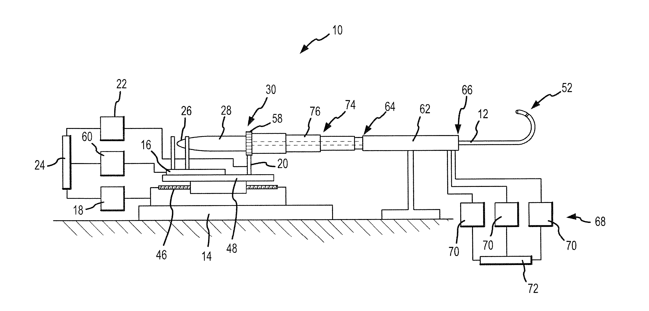
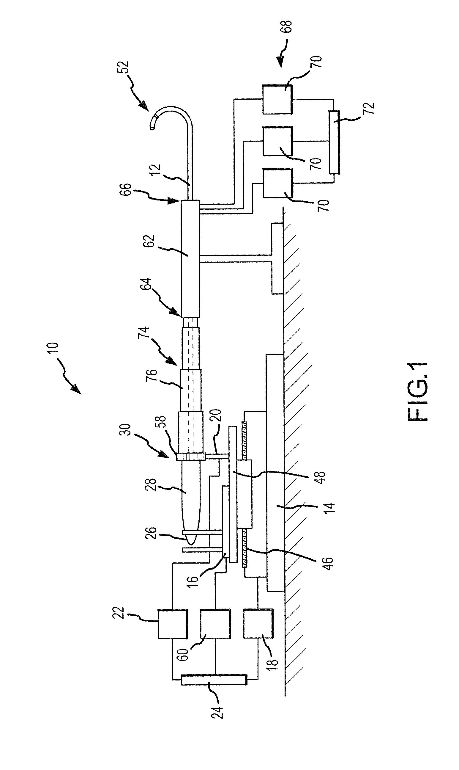
[0030]FIG. 1 schematically illustrates an embodiment of a robotic surgical system 10 for robotic manipulation and control of a medical device 12. Medical device 12 is preferably a catheter, which may be any type of catheter, including, by way of example only and without limitation, an ablation catheter, a guide wire catheter, an introducer catheter, a probe, or a stylet. It should be understood, however, that any other therapeutic, diagnostic, or assistive medical device may be controlled by robotic surgical system 10 without departing from the scope of the present invention. Such other devices include, but are not limited to, syringes, electrophoresis devices, iontophoresis devices, transdermal pharmaceutical delivery devices, myoblast delivery devices, stem cell delivery devices, ablation devices, stents, and pacemaker leads, which may be carried on or delivered by a catheter. It should further be understood that robotic surgical system 10 may be used to manipulate and control mor...


PUM


Abstract

A method of calibrating a robotic device, such as a cardiac catheter, includes oscillating the device on an actuation axis by applying an oscillation vector at an oscillation frequency. While oscillating, a location of the device is periodically measured to generate a plurality of location data points, which may express the location of the device relative to a plurality of measurement axes. The location data points are then processed using a signal processing algorithm, such as a Fourier transform algorithm, to derive a transfer function relating a position of the device to a movement vector for the actuation axis. The transfer function may be resolved into and expressed as a calibration vector for the actuation axis, which may include one or more components, including zero components, directed along each of the measurement axes. The process may be repeated for any actuation axes on which calibration is desired.

Description

CROSS-REFERENCE TO RELATED APPLICATIONS [0001] This application is a continuation in part of U.S. application Ser. No. 11 / 139,908, filed 27 May 2005, now pending. This application is also related to U.S. application Ser. No. 11 / 647,300, filed 29 Dec. 2006, now pending, U.S. application Ser. No. 11 / 647,298, filed 29 Dec. 2006, now pending, U.S. application Ser. No. 11 / 647,272, filed 29 Dec. 2006, now pending, U.S. application Ser. No. 11 / 647,296, filed 29 Dec. 2006, now pending, U.S. application Ser. No. 11 / 647,297, filed 29 Dec. 2006, now pending, and U.S. application Ser. No. 11 / 647,304, filed 29 Dec. 2006, now pending. The foregoing are hereby incorporated by reference as though fully set forth herein.BACKGROUND OF THE INVENTION [0002] a. Field of the Invention [0003] The instant invention relates to robotically controlled devices employing positional feedback systems. In particular, the instant invention relates to a method for obtaining a transfer function in order to calibrate ...

Claims


Application Information

Patent Timeline
Patent Type & Authority Applications(United States)
IPC IPC(8): A61B5/00A61B19/00G01S15/00
CPCA61B1/0052A61M25/0133A61B5/7257A61B19/22A61B19/2203A61B19/5244A61B2017/003A61B2017/00699A61B2017/00703A61B2017/00725A61B2017/22075A61B2017/3409A61B2019/2211A61B2019/2242A61B2019/2276A61B2019/5251A61B2019/5253A61B2560/0223A61M25/0105A61B19/20A61B5/042A61B90/10A61B2034/742A61B2034/2053A61B34/20A61B34/70A61B34/71A61B2034/301A61B34/30A61B2034/2051A61B5/283
Inventor HAUCK, JOHN A.
Owner ST JUDE MEDICAL ATRIAL FIBRILLATION DIV
Why Eureka
Try Eureka