Cardiac Magnetic Field Diagnostic Apparatus and Evaluating Method of Three-Dimensional Localization of Myocardial Injury

a diagnostic apparatus and magnetic field technology, applied in the field of cardiac magnetic field diagnostic apparatus and an evaluation method of three-dimensional localization of myocardial injury, can solve the problems of invading the living body, and the inability of conventional diagnostic methods to display the absolute position of myocardial injury on the three-dimensional spa

Inactive Publication Date: 2008-02-07
IWATE UNIVERSITY
View PDF5 Cites 25 Cited by
  • Summary
  • Abstract
  • Description
  • Claims
  • Application Information

AI Technical Summary

Benefits of technology

[0079] As mentioned above, according to the present invention, from three-dimensional distribution of current densities of the chest of a subject, data relatively displaying a myocardial injury, such as QRS difference, T-wave vector, or RT-dispersion is displayed three-dimensionally and stereoscopically. Further, the data is reconstructed to a cardiac contour cubic diagram additionally-configured from three-dimensional distribution of current densities of the same subject, thereby enabling the absolute three-dimensional spatial display of the myocardial injury of the heart with noninvasiveness. The localization of the myocardial injury can be determined in diagnosis of a cardiac disease in a hospital or emergency room.
[0080] In particular, the present invention provides an advantageous method for diagnosing acute coronary syndromes (acute myocardial inju

Problems solved by technology

All the methods use the contrast medium applied to the radioactive isotope, ultrasonic waves, or magnetic resonance method, and are invasive for the living bod

Method used


Image

  • Cardiac Magnetic Field Diagnostic Apparatus and Evaluating Method of Three-Dimensional Localization of Myocardial Injury
  • Cardiac Magnetic Field Diagnostic Apparatus and Evaluating Method of Three-Dimensional Localization of Myocardial Injury
  • Cardiac Magnetic Field Diagnostic Apparatus and Evaluating Method of Three-Dimensional Localization of Myocardial Injury

Examples


first embodiment

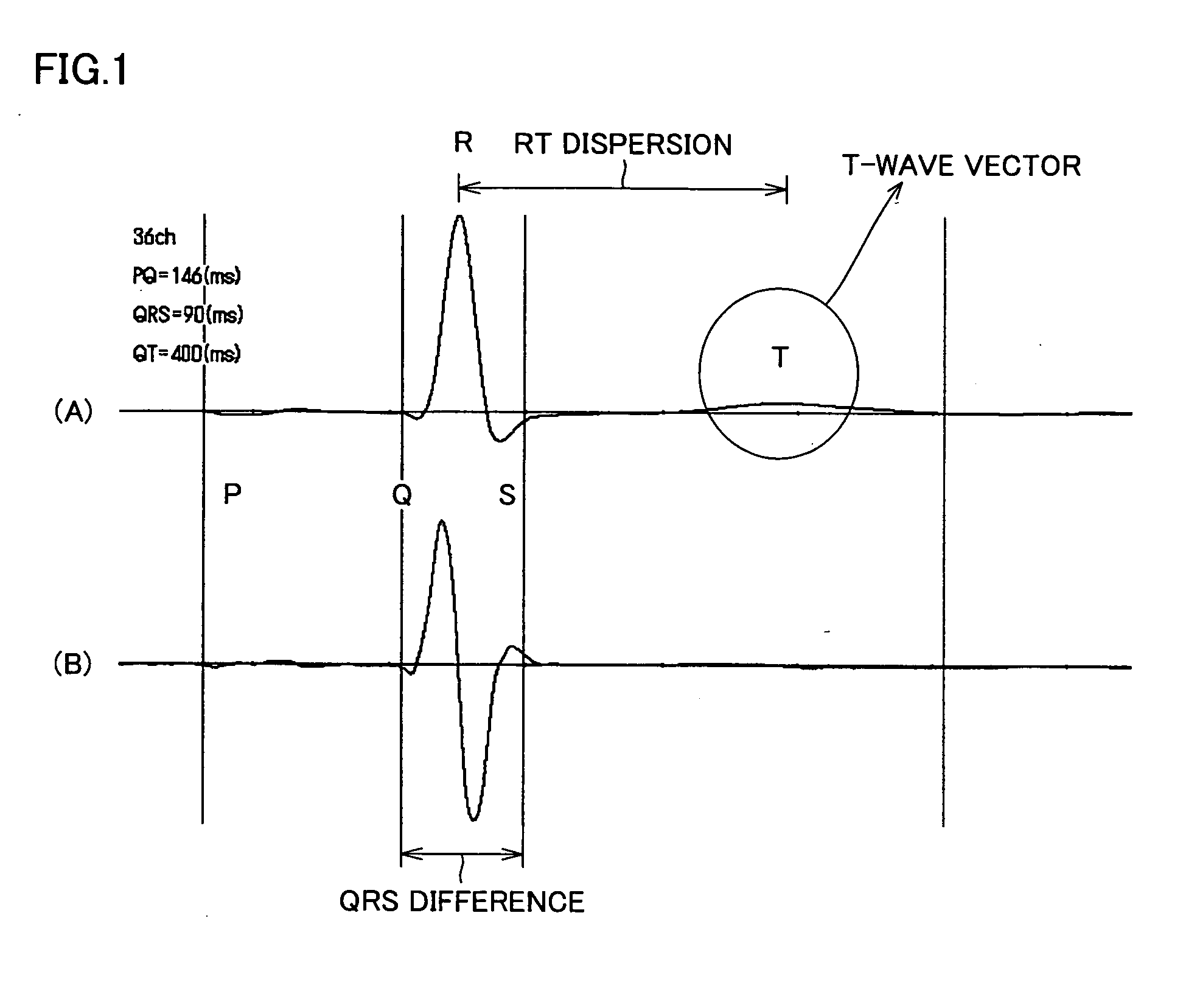
[0144] According to a first embodiment of the present invention, the QRS difference of magnetocardiography can be three-dimensionally displayed, thereby enabling the three-dimensional localization of a myocardial injury.

[0145]FIG. 1 is a waveform diagram showing actual waveforms of the magnetocardiography. Referring to FIG. 1, a description will be given of the principle of the first embodiment of the present invention.

[0146] In the actual waveforms of the magnetocardiography shown in FIG. 1, a waveform (A) corresponds to an actual waveform diagram of each channel of a cardiac magnetic-field measured with an SQUID fluxmeter, and a waveform (B) corresponds to a waveform diagram showing the QRS difference, which will be described later.

[0147] As mentioned above, the QRS waves reflect a cardiac electromotive force, and it is identified that the cardiac electromotive force is reduced at the portion where the myocardial injury such as cardiac infarction is caused. Therefore, three-dim...

second embodiment

[0248] According to the second embodiment of the present invention, the T-wave vector of the magnetocardiography can be three-dimensionally displayed, thereby enabling the determination of the three-dimensional spatial localization of the myocardial injury. Hereinbelow, the principle according to the second embodiment of the present invention will be described.

[0249] Referring back to FIG. 1, the actual waveform of the cardiac magnetic-field in (A) includes the T waves. As mentioned above, the T waves reflect the repolarization of the myocardium (particularly, the direction of repolarization). In the case of the healthy individual, the current vector of the QRS waves and the current vector of the T waves are in the same direction (approximately 45 degrees at the average of the healthy individual).

[0250] On the other hand, if the myocardium is damaged, the current vector of the T waves variously changes and, particularly, at the infarcted myocardium, it is just in the opposite dire...

third embodiment

[0281] According to the second embodiment of the present invention, the RT-dispersion of the magnetocardiography can be three-dimensionally displayed, thereby enabling the determination of the three-dimensional spatial localization of the myocardial injury. Hereinbelow, the principle according to the third embodiment of the present invention will be described.

[0282] Referring again to FIG. 1, the actual waveform of the cardiac magnetic-field in (A) includes R waves and T waves. As mentioned above, the RT time serving as the interval between the R waves and the T waves reflects the repolarization time of the myocardium. Further, in the case of the healthy individual, the repolarization time is approximately equal, and corresponds to the time fluctuation of the repolarization between the maximum time and the minimum time, that is, the RT-dispersion is 20 ms to 40 ms.

[0283] On the other hand, if the myocardium is damaged, the RT-dispersion, serving as the time difference of the repol...


PUM


Abstract

A cardiac magnetic field diagnostic apparatus for evaluating intracardiac three-dimensional localization of a myocardial injury by means of cardiac magnetic field measurement and a three-dimensional localization evaluating method of myocardial injury are disclosed. A magnetic field distribution measuring instrument (1) creates magnetic field distribution data by contactless magnetic field measurement on coordinates on the breast of a subject. An arithmetic operation unit (2) computers intracardiac three-dimensional current density distribution data from the magnetic field distribution data, draws a magnetic field integral cubic diagram as a cardiac contour cubic diagram according to the three-dimensional current density distribution data, creates data to draw the three-dimensional distribution of the QRS difference, the T-wave vector, or the RT dispersion of the same subject according to the three-dimensional current density distribution data, and reconstructs it on the cardiac contour. With this, evaluation of three-dimensional localization of a myocardial injury is possible.

Description

TECHNICAL FIELD [0001] The present invention relates to a cardiac magnetic field diagnostic apparatus and an evaluating method of three-dimensional localization of myocardial injury, and more particularly, to a cardiac magnetic field diagnostic apparatus that calculates a three-dimensional distribution of current densities of the heart from a cardiac magnetic field of a subject so as to configure a cardiac magnetic-field integral cubic diagram (cardiac contour cubic diagram), enables cardiac spatial recognition or configuration of an excitation propagating locus, and reconfigures the three-dimensional localization of a myocardial injury in the same space of the subject, and an evaluating method of three-dimensional localization of myocardial injury. BACKGROUND ART [0002] Diagnosis of a myocardial injury is important for diagnosis of diseases of coronary arteries such as cardiac infarction, because the lesion of the coronary arteries can be estimated by determining the localization o...

Claims


Application Information

Patent Timeline
IPC IPC(8): A61B5/05A61B5/04
CPCA61B5/04007A61B6/503A61B5/4519A61B5/243A61B5/05A61B5/055A61B5/24A61B5/318
Inventor NAKAI, KENJIKAWAZOE, KOHEIKOBAYASHI, KOICHIROITO, MANABUNAKAMURA, YOAHIHIKOSHIMIZU, TAKAYUKIYOSHIZAWA, MASAHITO
Owner IWATE UNIVERSITY
Why Eureka
Try Eureka