Medical balloon and method of making the same

a balloon and balloon technology, applied in the field of medical devices, can solve the problems of reducing the effectiveness of a stent, complicating the withdrawal of the catheter, and difficult passage of the catheter through the narrow vasculature of the patient,

Active Publication Date: 2008-02-07
WL GORE & ASSOC INC
View PDF15 Cites 65 Cited by
  • Summary
  • Abstract
  • Description
  • Claims
  • Application Information

AI Technical Summary

Benefits of technology

[0009]Accordingly, the present invention is directed to a medical balloon and method of making the same that substantially obviates one or more of the problems due to limitations and

Problems solved by technology

Because the non-compliant material has a limited ability to expand, the uninflated balloon must be made sufficiently large so that, when inflated, the balloon has sufficient working diameter to compress the stenosis and open the patient's passageway.
However, a large profile, non-compliant balloon can make the catheter difficult to advance through the patient's narrow vasculature because, in an uninflated condition, such balloons form flat or pancake shaped wings which extend radially outward.
These wings on the deflated balloon are undesirable because they result in an increased balloon profile which can complicate withdrawing the catheter after stent deployment.
Although stents have been used effectively f

Method used


Image

  • Medical balloon and method of making the same
  • Medical balloon and method of making the same
  • Medical balloon and method of making the same

Examples


example 1

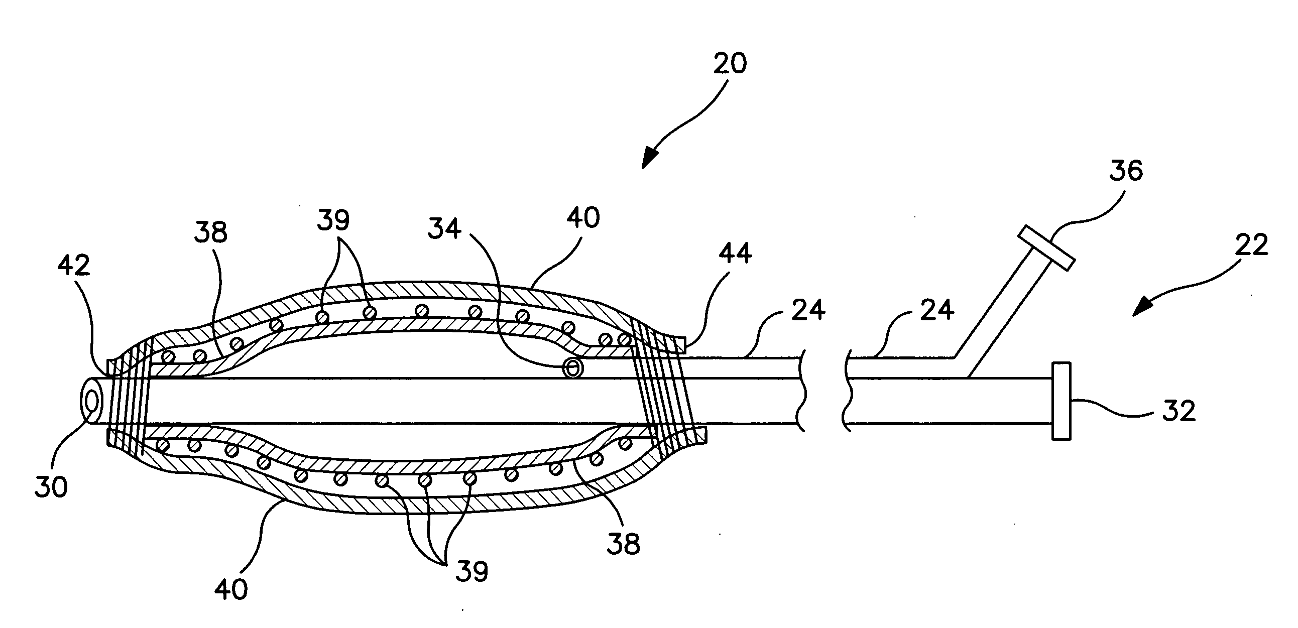
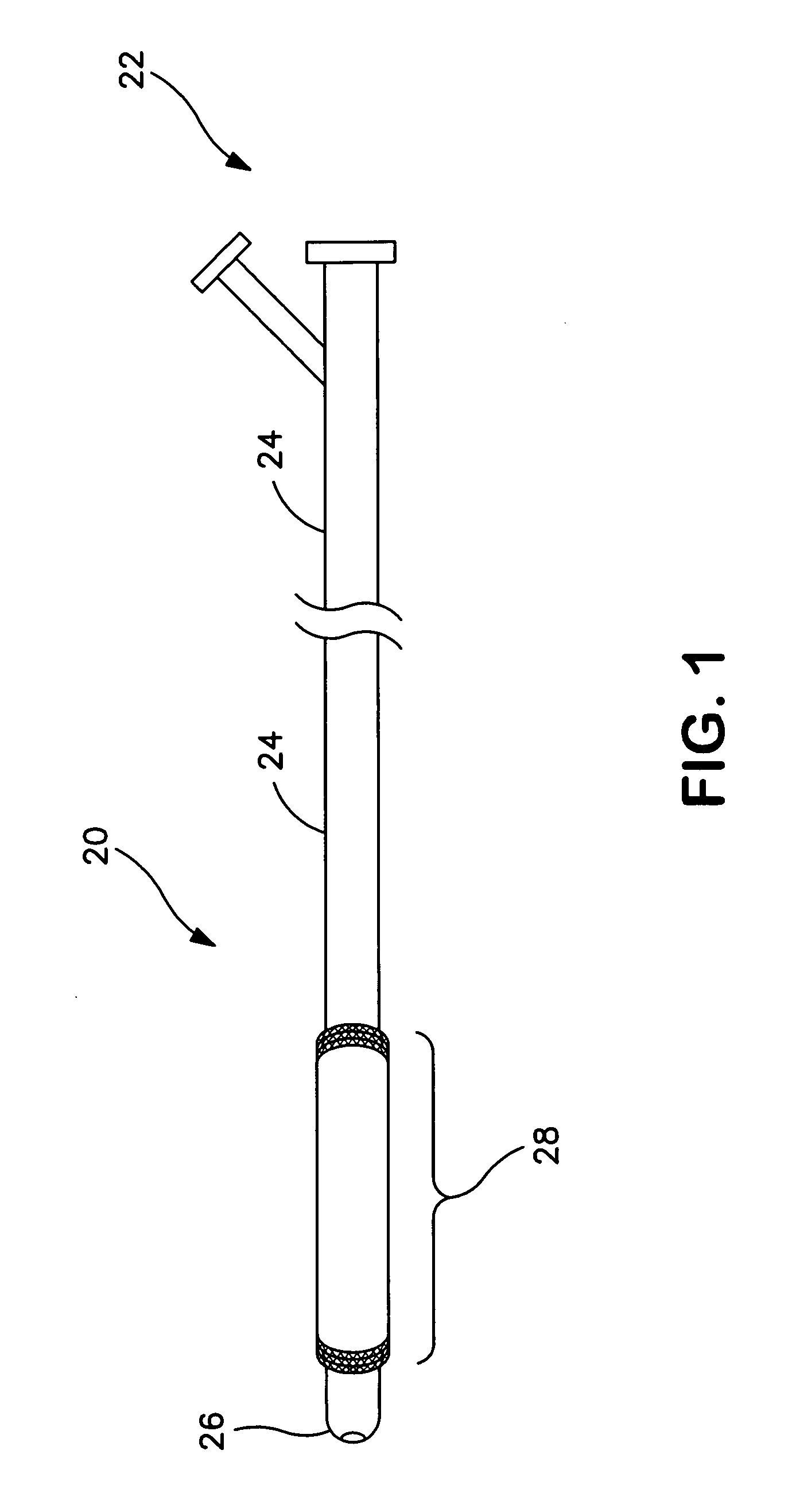
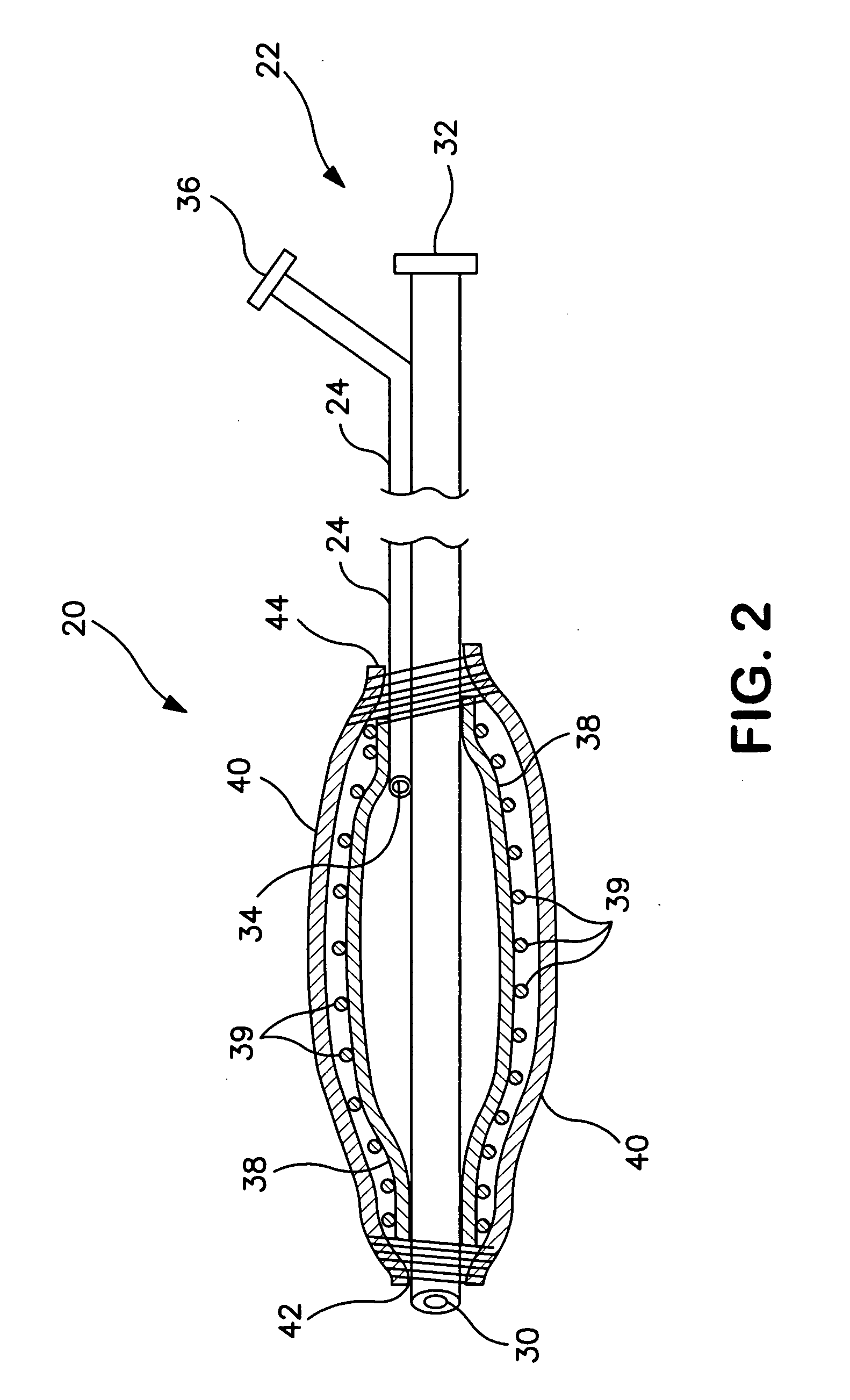
[0060]A preferred embodiment of a high-pressure, non-elastic balloon having a fiber reinforcement and an external elastomeric sheath is detailed in Example 1. This example follows the process flow outlined according to FIG. 6.

[0061]1. An over the wire catheter having a non-elastic balloon of PET with an inflated body diameter of about 8mm, a body length of about 40mm, shoulder lengths of about 18 mm (20° included angle), leg lengths of about 7 mm and leg diameters of about 1.4 mm (from Advanced Polymers Inc., N.H.), was positioned onto a mult-axis filament winding machine. A stiffening wire or mandrel was threaded through the guidewire lumen of the catheter so that approximately 10 cm of the wire extended from both ends of the catheter. The stiffening wire was joined to the catheter proximal end (hub) by tightening the catheter's Tuohy-Borst compression fitting. The opposite, distal end of the catheter was joined to the stiffening wire by pre-wrapping the wire with an ePTFE film. Th...


PUM

PropertyMeasurementUnit
Fractionaaaaaaaaaa
Fractionaaaaaaaaaa
Elastomericaaaaaaaaaa

Abstract

Reinforced angioplasty balloon having an external elastic sheath. The elastic sheath maintains, along its length, a substantially uniform circular cross-section during balloon inflation and forces a deflated balloon into a compacted, substantially circular, wingless profile.

Description

BACKGROUND OF THE INVENTION[0001]1. Field of the Invention[0002]This invention relates generally to medical devices and methods of making the same. More particularly the invention relates to balloons for use in medical applications, such as balloons for use with catheters.[0003]2. Discussion of the Related Art[0004]As an alternative to open-heart, coronary bypass surgery, a technique referred to as coronary transluminal angioplasty has been developed. In carrying out this procedure, a dilatation catheter having a balloon on the distal end is routed through the vascular system to a location within a coronary artery containing a stenotic lesion. Following placement of the balloon across the lesion, a fluid is introduced into the proximal end of the catheter and is used to inflate the balloon to a predetermined relatively high pressure whereby the lesion is compressed into the vessel wall restoring patency to the previously occluded vessel.[0005]In conventional stent deploying balloon ...

Claims


Application Information

Patent Timeline
IPC IPC(8): A61M29/00A61F2/958
CPCA61L29/085A61M25/1029A61M25/1034A61M2025/1031A61M2025/1075A61M2025/1081A61M2025/1084A61M25/104C08L27/18
Inventor CAMPBELL, CAREY V.GREENE, JOEL M.HOLDEN, LAWRENCE D.WILEY, WILLIAM HAMMOND
Owner WL GORE & ASSOC INC
Why Eureka
Try Eureka