
Method for forming micro blind via on a copper clad laminate substrate utilizing laser drilling technique

a laser drilling and laminate substrate technology, applied in the direction of manufacturing tools, dielectric characteristics, light absorption dielectrics, etc., can solve the problems of unavoidable movement of research and development of printed circuit boards, increased process time, and reduced throughpu

Inactive Publication Date: 2008-02-14
NAN YA PRINTED CIRCUIT BOARD CORPORATION
View PDF9 Cites 16 Cited by
  • Summary
  • Abstract
  • Description
  • Claims
  • Application Information

AI Technical Summary

Benefits of technology

[0013]It is one object of the present invention to provide an improved method for directly forming a micro blind via on a one side of a double-side copper clad laminate substrate utilizing laser drilling technique without the need of forming a copper window in advance.

Problems solved by technology

As there is demand for electronic products to be lighter, smaller, and portable, research and development of printed circuit boards is unavoidably moving toward a direction of miniaturization, higher integration, lower thickness, and the use of multiple layers.
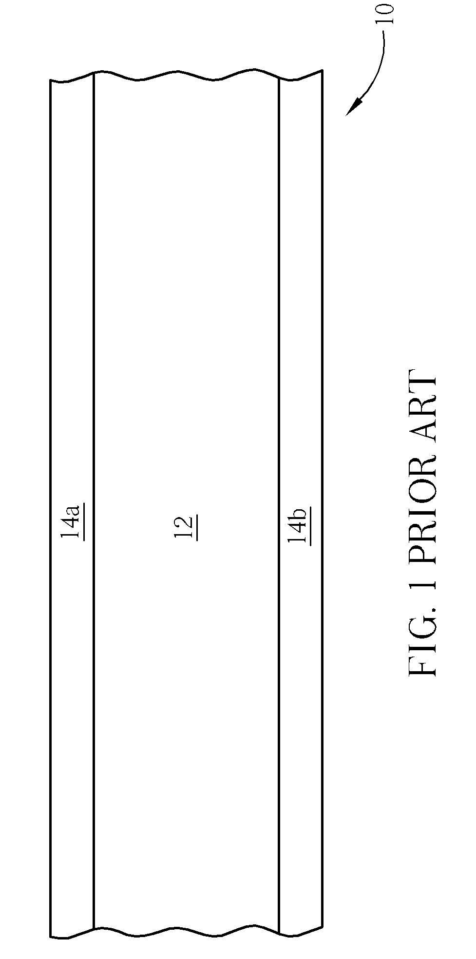
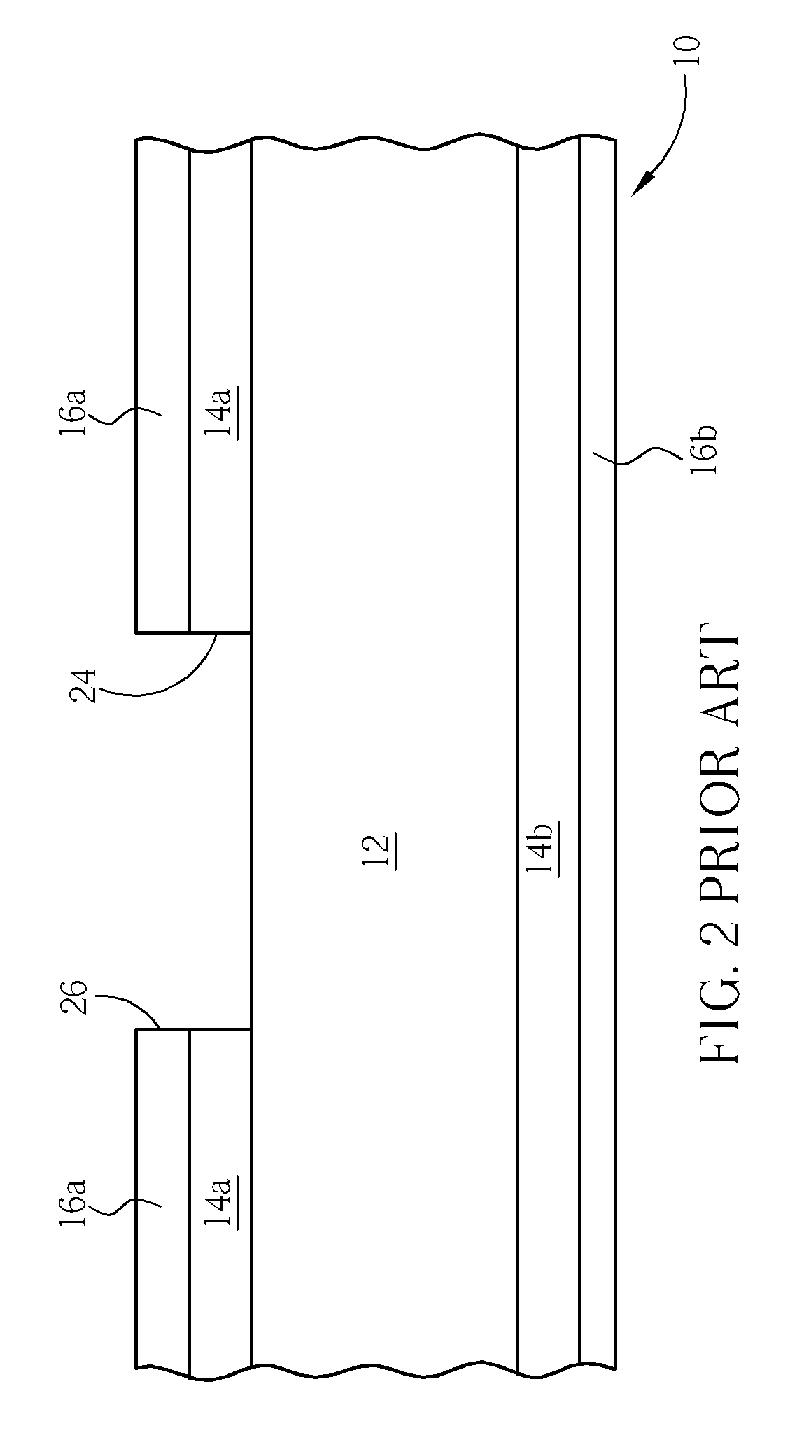
The above-described prior art method has a drawback in that the copper window 24 is required before performing the laser drilling process in order to define the laser burning area in advance.
Therefore, it requires one additional exposure / development step and one more copper etching step, thus increases the process time and reduces the throughput.
The additional exposure / development step and copper etching step also increases the production cost.

Method used


Image

  • Method for forming micro blind via on a copper clad laminate substrate utilizing laser drilling technique
  • Method for forming micro blind via on a copper clad laminate substrate utilizing laser drilling technique
  • Method for forming micro blind via on a copper clad laminate substrate utilizing laser drilling technique

Examples


Embodiment Construction

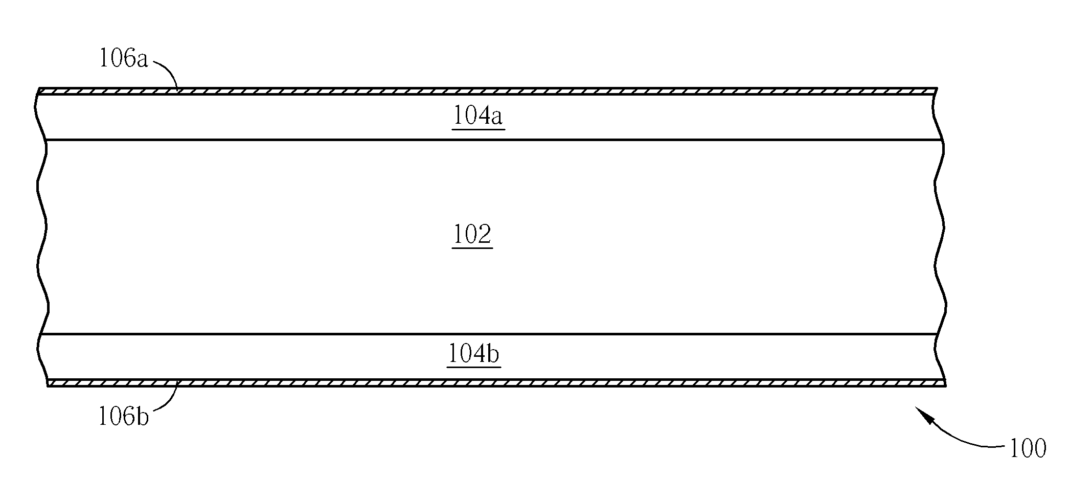
[0018]Please refer to FIGS. 6-12. FIGS. 6-12 are schematic, cross-sectional diagrams illustrating a preferred exemplary process of directly forming a micro blind via on a double-side copper clad substrate utilizing laser drilling technique in accordance with one preferred embodiment of this invention. As shown in FIG. 6, a double-side copper clad laminate (CCL) substrate 100 is provided. The CCL substrate 100 comprises an intermediate base layer 102 and copper films 104a and 104b sandwiching about the intermediate base layer 102. The intermediate base layer 102 may be made of prepreg or any other suitable dielectric insulating materials.

[0019]As shown in FIG. 7, a laser absorbing layer 106a and laser absorbing layer 106b are formed on the copper films 104a and 104b, respectively. The laser absorbing layer 106a and laser absorbing layer 106b is capable of absorbing a laser radiation with a pre-determined laser wavelength. According to the preferred embodiment of this invention, the l...


PUM

PropertyMeasurementUnit
Fractionaaaaaaaaaa
Thicknessaaaaaaaaaa
Dielectric polarization enthalpyaaaaaaaaaa

Abstract

This invention provides a method for forming a micro blind via on a copper clad laminate (CCL) substrate. A CCL substrate having a dielectric layer sandwiched by a first copper layer and a second copper layer is prepared. A laser absorbing layer is formed on the first copper layer. The laser absorbing layer is subjected to laser drilling. A micro blind via is drilled into the first copper layer and the dielectric layer in one step.

Description

BACKGROUND OF THE INVENTION [0001]1. Field of the Invention[0002]The present invention relates to a process for manufacturing a circuit board and, more particularly, to a method for forming a micro blind via on a one side of a double-side copper clad laminate substrate utilizing laser drilling technique. According to this invention, it is not necessary to form a copper window during the fabrication of the micro blind via.[0003]2. Description of the Prior Art[0004]In recent history, printed circuit boards (PCBs) have been widely used for carrying various electronic components and devices. As there is demand for electronic products to be lighter, smaller, and portable, research and development of printed circuit boards is unavoidably moving toward a direction of miniaturization, higher integration, lower thickness, and the use of multiple layers.[0005]In general, printed circuit boards having circuit layouts on both sides of the circuit boards have been widely used in numerous electri...

Claims


Application Information

Patent Timeline
IPC IPC(8): B32B38/04
CPCB23K26/385B23K2201/40B23K2203/16B32B2310/0843B32B2457/08H05K3/0035Y10T156/1082H05K3/385H05K3/421H05K2201/0112H05K2203/0315H05K3/0038B32B2038/042B23K26/389B23K2101/40B23K2103/16B23K2103/172
Inventor HSU, HUNG-ENLI, MING-CHIA
Owner NAN YA PRINTED CIRCUIT BOARD CORPORATION
Learn More