Electroplating cell with hydrodynamics facilitating more uniform deposition on a workpiece with through holes during plating

a technology of hydrodynamics and plating cells, which is applied in the direction of conductive pattern reinforcement, electronic components, printed circuit manufacturing, etc., can solve the problems of low solution movement rate, adversely affecting the performance of finished printed wiring board interconnection, and creating areas where copper cannot be deposited, so as to facilitate uniform metal deposit distribution

Active Publication Date: 2008-02-14
FARADAY TECH INC
View PDF33 Cites 22 Cited by
  • Summary
  • Abstract
  • Description
  • Claims
  • Application Information

AI Technical Summary

Benefits of technology

[0028] Still another embodiment of the present invention particularly relates to controlling the hydrodynamics in a plating cell, to facilitate uniform metal deposit distribution across a high density interconnect printed circuit board using an electrochemical plating process.

Problems solved by technology

As the hole and via diameter decrease, the workpiece thickness increases, and the workpiece dimension increases, the most notable challenge for the quality of metal electrodeposits is the avoidance of non-uniform copper thickness distribution over board surfaces and within through holes, i.e. the challenge of leveling or throwing power, which can adversely affect the performance of the finished printed wiring board interconnect (Paunovic, M. and M. Schlesinger, 1998)2, (Ward, M., D. R. Gabe and J. N. Crosby, 1999a)3.
However, air sparging can create problems in the plating operation: the oxygen can oxidize components of the electrolyte, the oxygen can oxidize features and circuit patterns on the workpiece, air bubbles (106) may become trapped in features in the workpiece (102), creating areas where copper cannot be deposited, this method can generate low solution movement rates, which can result in burning of the workpiece (102) at high current densities, and as the air bubbles progress towards the top of the cell they grow in size and can create a non-uniform solution environment from the bottom of the workpiece to the top.
However, knife edge agitation still can result in non-uniformity of the deposited copper and adds complexity to plating cell design.
Furthermore, incorporation of knife edge movement in existing workpiece plating lines is difficult and costly.
However, the glancing effect described above applies in this case, leading to non-uniform flow of solution across the workpiece (102).
This contributes to non-uniform flow of solution across the workpiece (102).

Method used


Image

  • Electroplating cell with hydrodynamics facilitating more uniform deposition on a workpiece with through holes during plating
  • Electroplating cell with hydrodynamics facilitating more uniform deposition on a workpiece with through holes during plating
  • Electroplating cell with hydrodynamics facilitating more uniform deposition on a workpiece with through holes during plating

Examples


example 1

Comparison

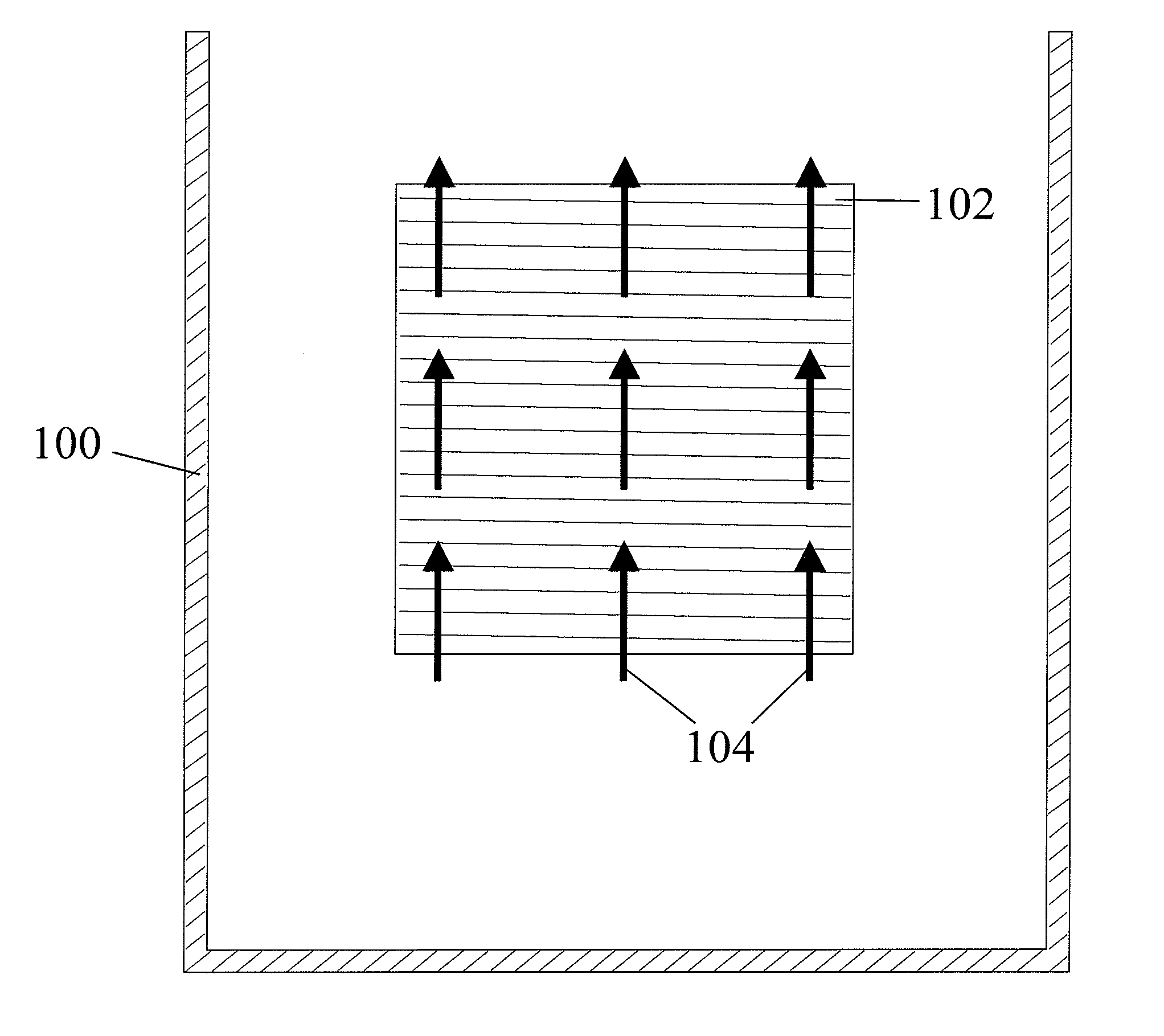
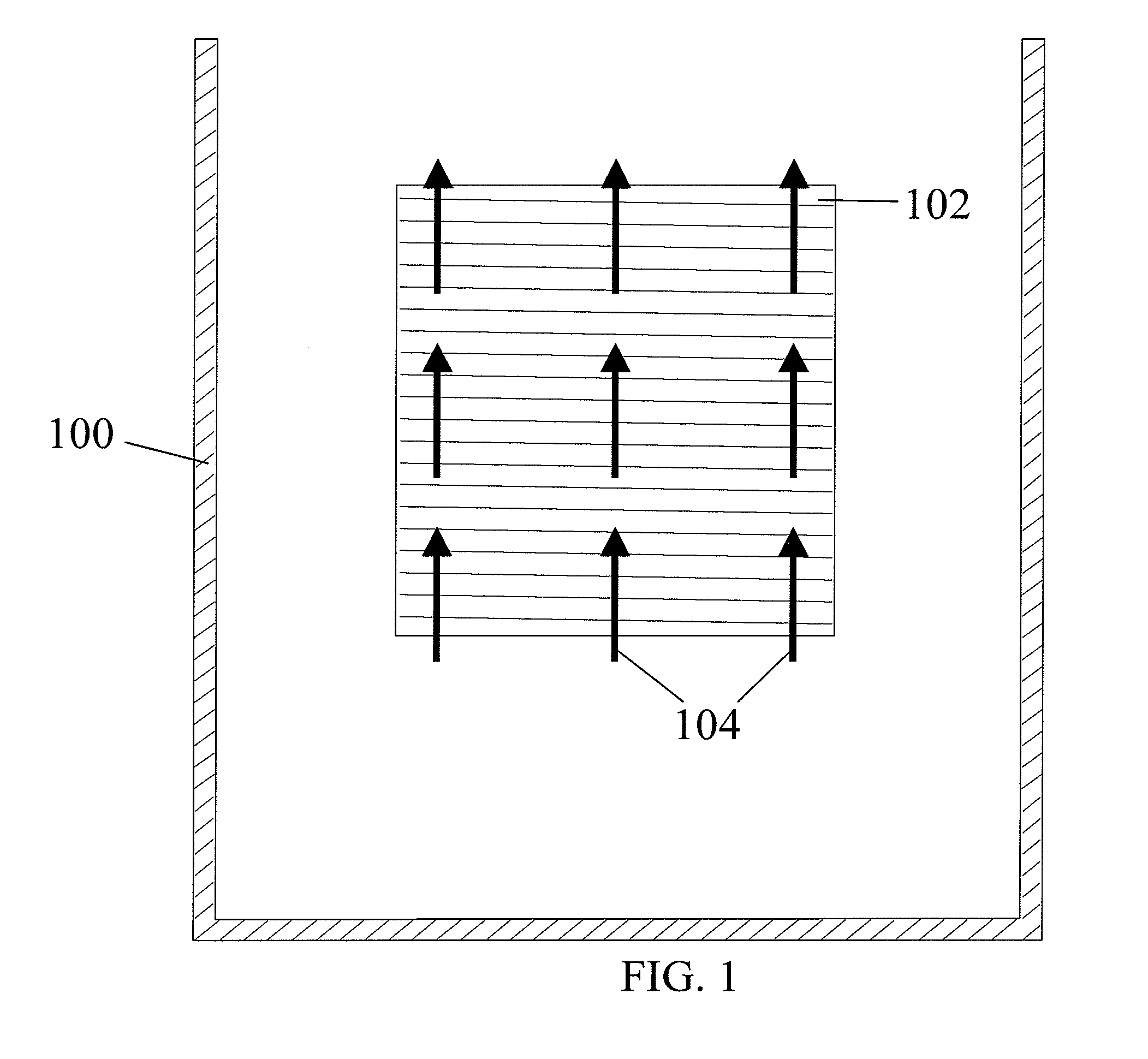
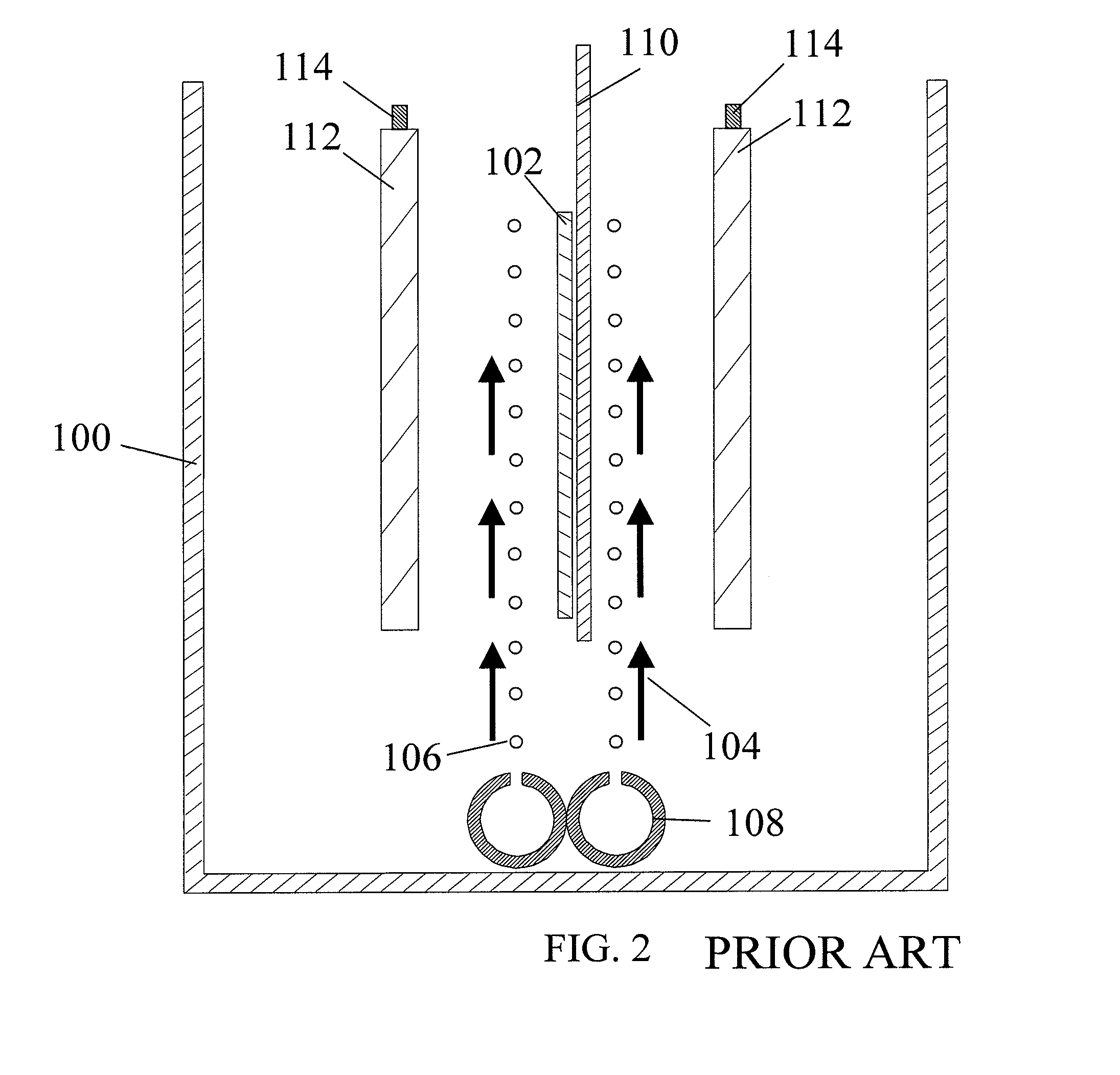
[0106] This example illustrates the use of the plating cell (100) with air sparging to deposit copper onto a workpiece (102), to demonstrate the prior art.

[0107] The experiments were conducted in the plating cell (100) shown in FIG. 2. An acid copper sulfate electrolyte containing ˜97 g / L CuSO4, 210-215 g / L of concentrated H2SO4, ˜63 ppm Cl−, and 350 ppm polyethylene glycol (PEG) was used as the copper electroplating bath. As known by those skilled in the art, the chloride / PEG acts as a suppressor and is not difficult to control. The plating bath does not contain difficult-to-monitor / control additives such as brighteners and / or levelers and hence the bath is considered “additive-free.” The plating bath temperature was maintained in the range of 22 to 25° C.

[0108] The initial experiments for plating cell (100) characterization were conducted on a stainless steel panel (450 mm×600 mm), as a workpiece (102). The copper plating process was controlled by DC current at 25 A / f...

example 2

[0111] This example illustrates the use of the plating cell (100) to deposit copper uniformly onto a workpiece (102), to demonstrate the effects of the various attributes of the plating cell (100) of the present invention, such as flow rate of electrolyte through the eductors (116), anodes (112) to workpiece (102) distance, oscillation (154) of the workpiece (102), and vibration (152) of the workpiece (102).

[0112] The experiments were conducted in the plating cell (100) shown in FIGS. 10 to 12. An acid copper sulfate electrolyte containing ˜97 g / L of CuSO4, 210-215 g / L of concentrated H2SO4, ˜63 ppm Cl−, and 350 ppm polyethylene glycol (PEG) was used as the copper electroplating bath for all experiments. The chloride / PEG is termed a suppressor and is not difficult to control. The plating bath does not contain difficult-to-monitor / control additives such as brighteners and / or levelers and hence we consider the bath as “additive-free.” The plating bath temperature was maintained in th...

example 3

[0119] This example illustrates the use of the plating cell (100) to deposit copper uniformly onto a workpiece (102), to demonstrate further effects of the various attributes of the plating cell (100), such as flow rate of electrolyte through the eductors (116), anodes (112) to workpiece (102) distance, use of an anode chamber (126), use of a porous fiber cloth (128), use of additional non-conducting shielding (130), and use of a baffle (138) under the anode chamber, on the current distribution over the panel workpiece (102) surface.

[0120] The experiments were conducted in the plating cell (100) shown in FIGS. 10 to 12. An acid copper sulfate electrolyte containing ˜97 g / L of CuSO4, 210-215 g / L of concentrated H2SO4, ˜63 ppm Cl−, and 350 ppm polyethylene glycol (PEG) was used as the copper electroplating bath for all experiments. The chloride / PEG acts as a suppressor and is not difficult to control. The plating bath does not contain difficult-to-monitor / control additives such as br...


PUM

PropertyMeasurementUnit
distanceaaaaaaaaaa
diameteraaaaaaaaaa
diameteraaaaaaaaaa

Abstract

A method and apparatus for establishing more uniform deposition across one or more faces of a workpiece in an electroplating process. The apparatus employs eductors in conjunction with a flow dampener member and other measures to provide a more uniform current distribution and a more uniform metal deposit distribution as reflected in a coefficient of variability that is lower than conventional processes.

Description

CROSS-REFERENCE [0001] This application is a continuation-in-part of U.S. application Ser No. 10 / 804,841 filed Mar. 19, 2004.FIELD OF THE INVENTION [0002] The present invention relates to a method and apparatus for controlling the hydrodynamics in a plating cell to facilitate more uniform deposition across a workpiece such as a printed circuit board. BACKGROUND OF THE INVENTION [0003] The continuing miniaturization of electronic devices is driving the design of interconnects in the direction of finer pitch surface tracks, smaller diameter through holes and vias, and thicker workpieces to provide increased circuit densities (Paunovic, M. and M. Schlesinger, 2000)1. This trend has significant implications for the electronics industry which must ensure that the metal electrodeposition process meets the functionality and quality requirements of these advanced workpiece device designs. These workpieces include printed circuit boards, chip scale packages, wafer level packages, printed wir...

Claims


Application Information

Patent Timeline
Patent Type & Authority Applications(United States)
IPC IPC(8): C25D17/00C25D5/08C25D5/00C25D21/10H05K3/24
CPCC25D5/08C25D21/10Y10S205/92C25D17/001C25D17/008H05K3/241
Inventor GEBHART, LAWRENCE E.TAYLOR, E. JENNINGS
Owner FARADAY TECH INC
Why Eureka
Try Eureka