Lens assembly with actuating means and auto-focus controlling apparatus having the same

a technology of actuating means and lens barrel, which is applied in the direction of mountings, focusing aids, instruments, etc., can solve the problems of unstability operation of lens units, difficulty in fine focusing control or adjustment, and lens unit size, so as to reduce the whole dimension or size of the lens barrel, less current, and less current

Inactive Publication Date: 2008-02-14
DIOSTECH
View PDF3 Cites 73 Cited by
  • Summary
  • Abstract
  • Description
  • Claims
  • Application Information

AI Technical Summary

Benefits of technology

[0014]It is an object of the present invention to provide a lens assembly which makes a focusing stably and finely and a driving only less currents compared to the conventional ones by arranging a driving actuator closely along an outside of the lens barrel and thereby reducing the whole dimension or size of the lens barrel, and an auto-focus controlling apparatus including the lens assembly. Such a closely configuration prevents the lens assembly from damaging owing to outside shocks and makes the lens barrel operated with less currents compared to the conventional ones. Electrical power is supplied with the driving coil through brushes each of which is formed respectively on and beneath a housing of the auto-focus controlling apparatus of the present invention. Therefore, it is possible to apply voltage or currents to the driving actuator much stably compared to through a semi-circular leaf spring in the conventional one.
[0015]It is another object of the present invention to provide a lens assembly having a driving means as a unit and an auto-focus controlling apparatus having the lens assembly. The camera module can be manufactured conveniently through such configuration. Besides, the components in the driving source are hardly damaged in the course of operating the apparatus. Especially, since the lens assembly comprises an elastic means which is arranged along the intermediate outside of the lens barrel accommodating the lens unit and is moved dependently on the lens barrel, the arrangement of the driving actuator limits the movement of the elastic means and thereby preventing the elastic means damaging during the reciprocating motion upwardly and downwardly of the lens assembly in case operating the auto-focus controlling apparatus. Besides, the auto-focus controlling apparatus can be manufactured by interconnecting the housing to the lens assembly through threaded couplings in producing the camera module. Therefore, it is possible to increase the convenience and productivity in manufacturing the camera module.

Problems solved by technology

However, such mechanical operation causes inevitably static-dynamic errors resulted from a friction between the motor and the gear, mechanical deformation, backlash, and the likes.
Therefore, it is very difficult or impossible to control or adjust finely focusing and to make a small camera owing to the space occupied by the motor and the gear in such an apparatus.
In case of manufacturing the camera module for satisfying the requirements such a miniaturization, a light-weigh, and a low-cost, the lens unit for achieving the focusing and / or zooming function is operated unstably and the components constituting the lens assembly may be damage easily because the lens unit is connected to the lens barrel through a single pin.
Accordingly, the conventional auto-focus controlling apparatus must have at least dimension which add the diameter of the lens barrel to the width of the driving source, which prevents the auto-focus controlling apparatus with much smaller size from being manufactured and causes the auto-focus controlling apparatus to have limitation in the efficiency of the power consumption.
Moreover, since each component in the driving source is arranged along the lens barrel without fixing firmly to it, it is very difficult to connect such arranged driving source to the lens barrel accommodating the lens unit in manufacturing the auto-focus controlling apparatus.

Method used


Image

  • Lens assembly with actuating means and auto-focus controlling apparatus having the same
  • Lens assembly with actuating means and auto-focus controlling apparatus having the same
  • Lens assembly with actuating means and auto-focus controlling apparatus having the same

Examples


Embodiment Construction

[0034]Reference will now be made in detail to the illustrated embodiment of the present invention, which is illustrated in the accompanying drawings.

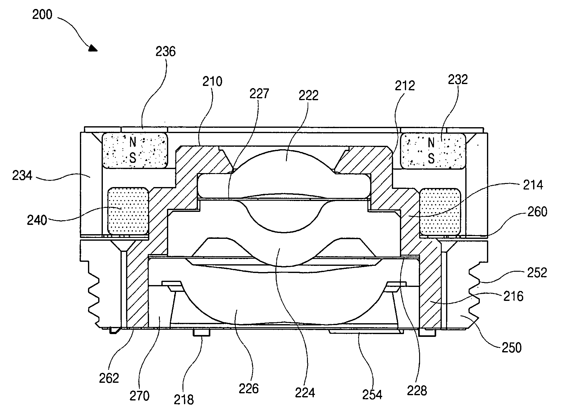
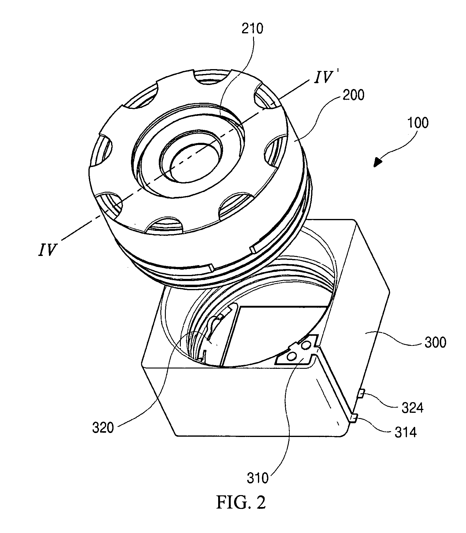
[0035]FIG. 2 is an exploded perspective view of an auto-focus controlling apparatus which comprises a lens assembly for focusing and a housing accommodating the lens assembly according to the present invention. As shown in FIG. 2, an auto-focus controlling apparatus 100 of the present invention comprises a lens assembly 200 which includes a lens barrel 210 with a hollow top center for accommodating the a lens unit and a housing accommodating the lens barrel for auto-focusing. The lens unit includes one or more lenses each of which preferably has a different diameter, respectively. According to one embodiment of the present invention, the lens assembly 200 has screw threads, which corresponds to screw threads formed in the lower inside of the housing 300, in the lower outside thereof so that the lens assembly 200 can be accommodated with...


PUM


Abstract

A lens assembly has a driving actuator which includes a magnet, a yoke and a coil and is formed along a lens barrel that accommodates a lens unit for focusing and an auto-focus controlling apparatus comprises the lens assembly for camera module. The magnet or the coil has an internal diameter smaller than a maximal diameter of the lens barrel. Therefore, it is possible to manufacture much smaller lens assembly according to the present invention compared to the conventional ones and to reduce the possibility of component damages in the lens assembly in operating the camera module.

Description

BACKGROUND OF THE INVENTION[0001]This application claims the benefit of Korean Patent Application No. 2006-74622, filed on Aug. 8, 2006, in Korea, which is hereby incorporated by reference for all purposes as if fully set forth herein.[0002]1. Field of the Invention[0003]The present invention relates to a lens assembly and an auto-focus controlling apparatus including the lens assembly and more particularly, to a lens assembly for auto-focusing with a driving means and an auto-focus controlling apparatus accommodating the lens assembly mounted in a camera module which can be applied to a mobile communication device.[0004]2. Discussion of the Related Art[0005]A camera means a device for taking pictures or capturing images through a plurality of lenses by adjusting relative distances among the lenses and thereby focusing the lenses of the camera. A conventional widely-used auto-focus controlling apparatus for a camera has adopted a mechanical operation by a gear which turns a rotation...

Claims


Application Information

Patent Timeline
Patent Type & Authority Applications(United States)
IPC IPC(8): G02B7/04
CPCG02B7/08G03B13/32H04N23/00
Inventor YOON, YOUNG-KOIN
Owner DIOSTECH
Why Eureka
Try Eureka