Blasting apparatus for outer surface of pipe

a technology for outer surfaces and blasted pipes, which is applied in the direction of grinding/polishing apparatus, grinding machine components, manufacturing tools, etc., can solve the problems of poor operability, degrading operability, and hygiene problems, and achieve the effect of reducing dust particles, remarkably improving operation environment, and easy movemen

Inactive Publication Date: 2008-02-14
HITACHI PLANT TECH LTD
View PDF9 Cites 15 Cited by
  • Summary
  • Abstract
  • Description
  • Claims
  • Application Information

AI Technical Summary

Benefits of technology

[0008] The present invention is made in view of the above circumstances, and has an object to provide a blasting apparatus for an outer surface of a pipe, which is capable of efficiently grinding the outer surface of a pipe with excellent operability.
[0023] According to the blasting apparatus for an outer surface of a pipe of the present invention, the blast head containing the nozzle which ejects the blast material and the suction port which sucks the blast material used for grinding and the dust particles is guided to be movable in the longitudinal direction and the circumferential direction of the outer surface of the pipe. Therefore, the used blast material and dust particles can be sucked, the blast head can be easily moved along the outer peripheral surface of the pipe with a simple mechanism, and blasting treatment of the outer surface of the pipe can be efficiently performed under the clean environment.

Problems solved by technology

However, since the sand blasting technique as described in the above described Japanese Patent Application Laid-Open No. 9-109029 adopts the method of a worker moving a blast ejection nozzle on a surface to be treated by gripping the blast ejection nozzle, it is inefficient, and has the problem in hygiene.
Further, the worker performs an operation as he or she makes one round of a pipe, and there is the problem that when the pipe is laterally arranged, operability becomes extremely bad, and when the pipe is close to a wall surface even if it is vertically arranged, operability also degrades.

Method used


Image

  • Blasting apparatus for outer surface of pipe
  • Blasting apparatus for outer surface of pipe
  • Blasting apparatus for outer surface of pipe

Examples


Embodiment Construction

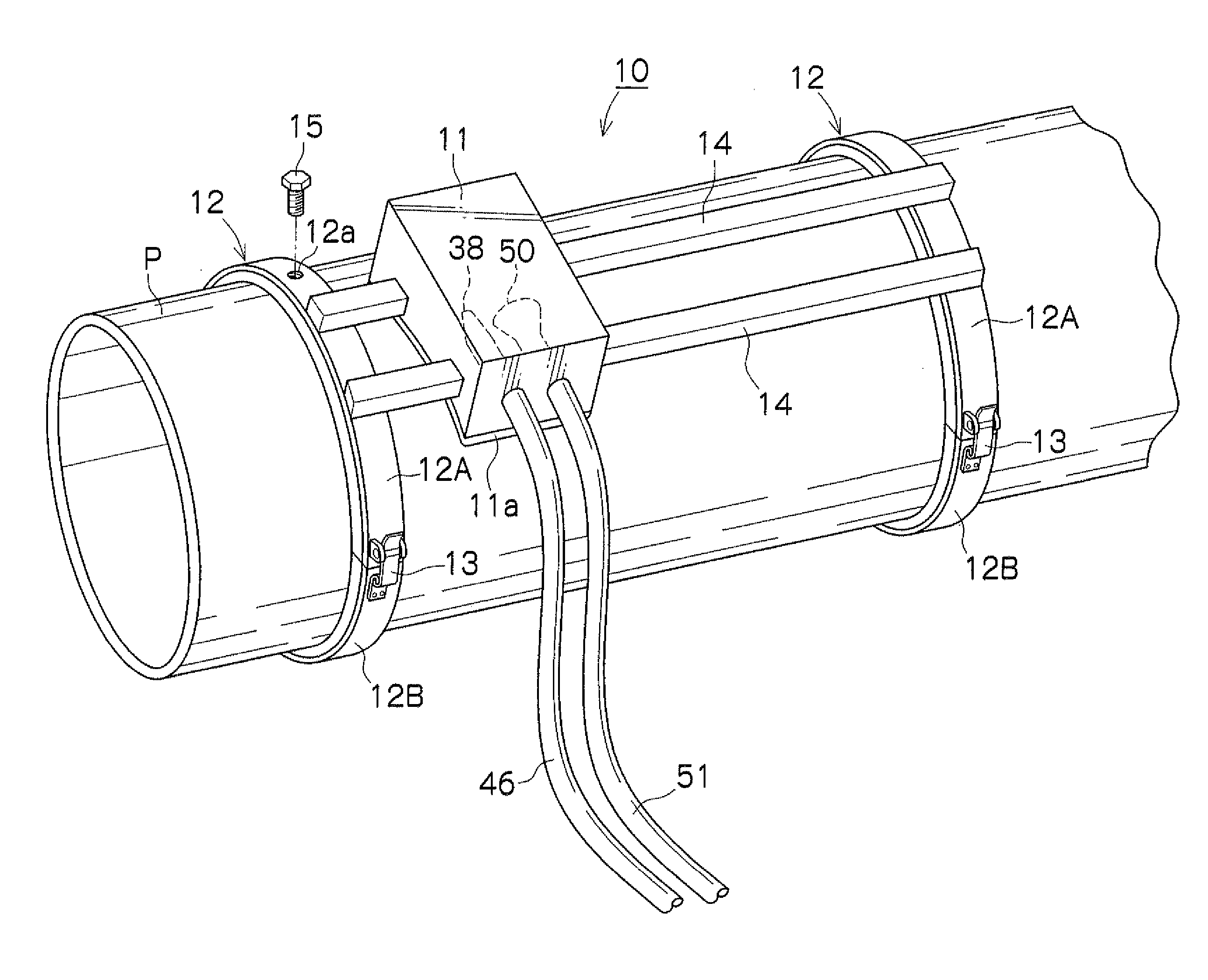
[0032] A preferred embodiment of a blasting apparatus for an outer surface of a pipe according to the present invention will now be described in detail with reference to the accompanying drawings. In this embodiment, explanation will be made with an example of a sponge blasting apparatus using a blast medium in a sponge piece form in which abrasives are contained in a porous elastic body as a blast material. The same members are assigned with the same numerals and characters in each drawing.

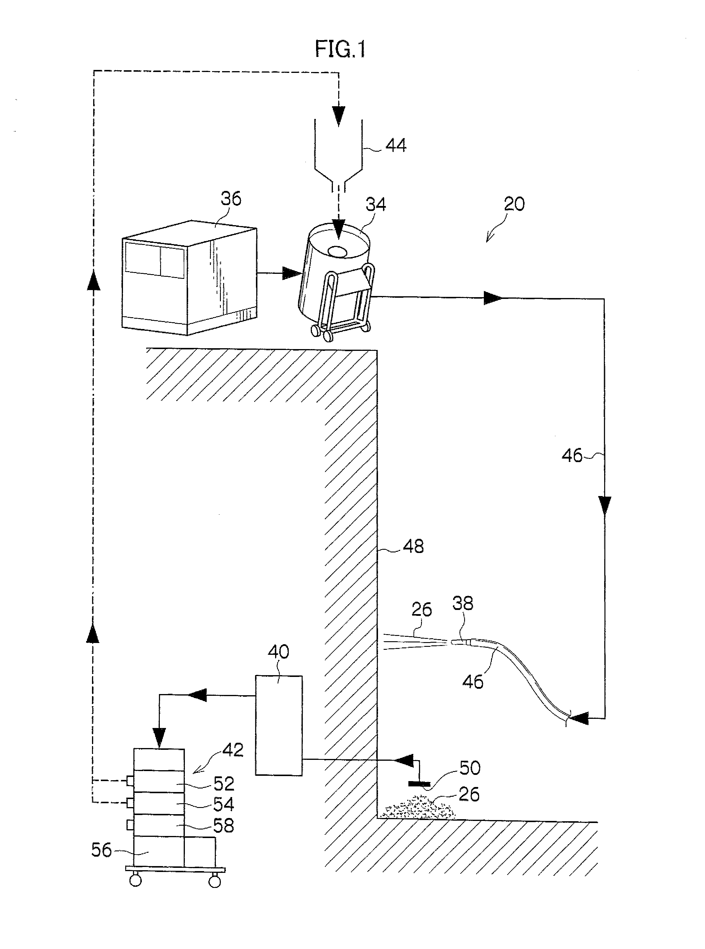
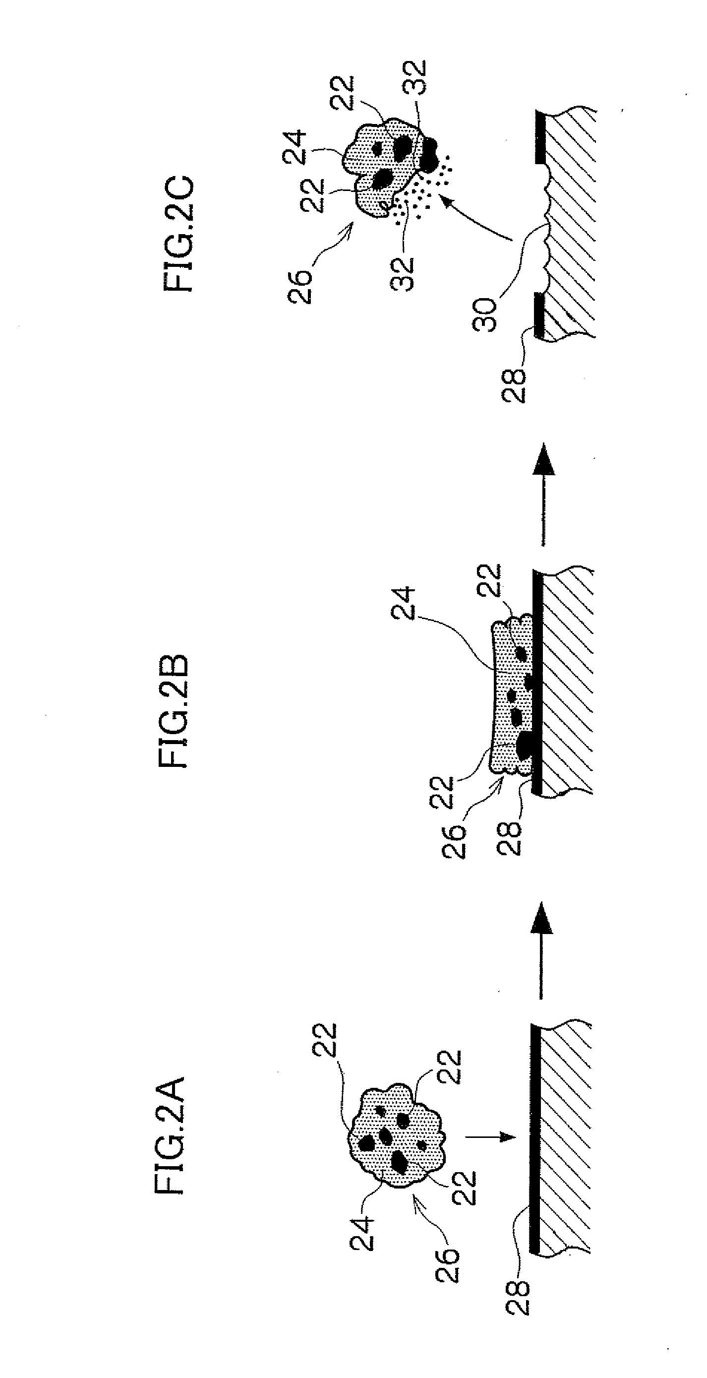
[0033]FIG. 1 is an explanatory view showing a basic structure of a sponge blasting apparatus 20 which is applied to the blasting apparatus for an outer surface of a pipe of the embodiment. Explaining the sponge blasting technique using the sponge blasting apparatus 20 first, the blast medium 26 as the blast material used in this technique is made by sticking abrasives (also called a grinding material in the case of an urea resin) of a different material (steel grit, alumina, star light, an urea ...


PUM


Abstract

The present invention provides a blasting apparatus for an outer surface of a pipe which ejects a blast material to an outer side of a pipe and grinds the outer surface, comprising: a blast head containing a nozzle which ejects the blast material and a suction port which sucks a blast material used for grinding and dust particles; a guide member which is provided along a longitudinal direction of the outer surface of the pipe, and guides the blast head along the longitudinal direction of the outer surface of the pipe; and a ring member which is a ring member constructed by connecting at least two half-split members and having an inside diameter larger than an outside diameter of the pipe, and which is disposed to have the pipe inserted through the ring member, holds the guide member, and guides the blast head in a circumferential direction of the outer surface of the pipe by turning in the circumferential direction on the outer surface of the pipe.

Description

BACKGROUND OF THE INVENTION [0001] 1. Field of the Invention [0002] The present invention relates to a blasting apparatus, and more particularly, relates to a Wasting apparatus for an outer surface of a pipe, which ejects a blast material to an outer surface of a pipe and grinds the outer surface of the pipe to perform surface preparation. [0003] 2. Description of the Related Art [0004] For example, a vent pipe (piping) placed inside a suppression chamber, which is a part of a nuclear reactor containment facility of an atomic power plant, has its outer peripheral surface and inner peripheral surface coated by recoating it with a plurality of coating materials excellent in corrosion resistance, decontaminability and the like. The repainting construction is carried out with about 10 years after the start of operation as a guide, and as a pre-construction of the repainting construction, grinding and decontaminating operations of grinding the coating film including radioactive substance...

Claims


Application Information

Patent Timeline
Patent Type & Authority Applications(United States)
IPC IPC(8): B24B49/00B24C3/06B24C3/32
CPCB24C3/06B24C9/003B24C3/32B24C11/00
Inventor SHIMIZU, TOKUOYANO, TETSUNORI
Owner HITACHI PLANT TECH LTD
Why Eureka
Try Eureka