Venting Assembly for a Casting Mould

a technology of die casting mould and venting assembly, which is applied in the direction of manufacturing tools,foundry moulding apparatus, other domestic objects, etc., can solve the problems of unsuitable heat treatment, high production cost, and high production cost, so as to increase the venting area, increase the projected area of the die, and increase the space of the di

Inactive Publication Date: 2008-02-21
WANDA TECH PTY
View PDF6 Cites 6 Cited by
  • Summary
  • Abstract
  • Description
  • Claims
  • Application Information

AI Technical Summary

Benefits of technology

[0037]A vent assembly according to the present invention differs from a conventional chill vent in that the main faces of the invention are at an angle, rather than parallel, to the die parting face. This more readily allows a limited space to have more than one vent aperture from the die cavity so as to increase the venting area without substantially increasing the die space. Moreover, the increase in the venting area does not increase the projected area of the die, since the main faces of the vent are at an angle to the die parting face. The present invention provides greater flow area for removal of gases from a die cavity.

Problems solved by technology

One problem which occurs particularly in a high pressure die casting (HPDC) process for the production of metal products is that gas is often trapped in isolated regions of the mould.
The entrapped gas forms porosity in the castings that can result in rejects and / or make them unsuitable for heat treatment.
However, the die castings are produced under very harsh conditions.
Any failure of the valve will introduce an additional maintenance cost due to the machine down-time.
The mechanical valves which currently serve in the industry are prone to malfunction and also have a high capital cost.
This small venting area restricts the efficiency of air ventilation.
It was found that the evacuation efficiency was very low, and not sufficient to achieve a sufficiently high vacuum level to produce good quality parts.
Since the orientation of the planar face of the conventional chill vent is parallel to the die parting face, the increase in the vent width will however accordingly increase the projected area occupied by injected metal in the die, thus increasing the force tending to separate the die parts, and therefore increasing the risk of die flash.
As a result, a conventional chill vent can not be effectively used as a vacuum ‘valve’.

Method used


Image

  • Venting Assembly for a Casting Mould
  • Venting Assembly for a Casting Mould
  • Venting Assembly for a Casting Mould

Examples


Embodiment Construction

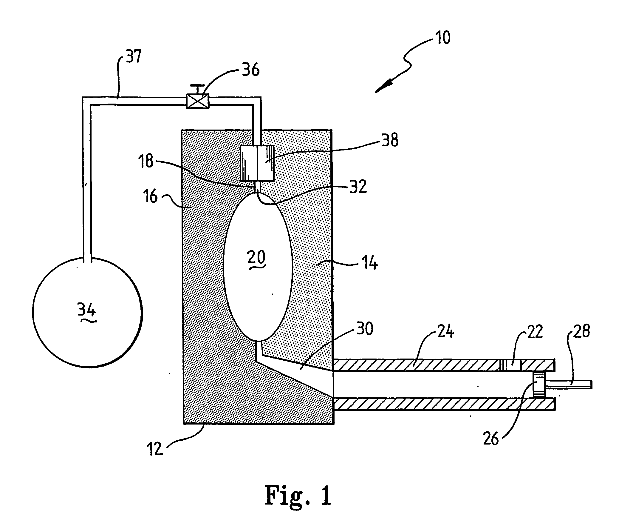
[0066]Referring to FIG. 1, the HPDC apparatus 10 comprises a die 12 comprising a fixed half die 14 and a moving half die 16 which are brought into mutual engagement by fluid actuated rams (not shown). The half dies 14 and 16 separate along a parting face 18. The half dies in engagement form a casting cavity 20 therebetween which has the shape of the product wished to be cast.

[0067]Molten metal is introduced to the cavity 20 by means of a high pressure injection system wherein metal is fed through a pour hole 22 into a shot sleeve 24 and a piston 26 on a plunger 28 first closes the pour hole 22 and then, in the same stroke, forces the desired amount of molten metal from the shot sleeve 24 through a runner 30 into the cavity 20. At the opposite end of the cavity a vent hole 32 allows gases and excess metal to escape the cavity.

[0068]Before molten metal is introduced to the cavity 20, the air in the cavity is evacuated through the vent hole 32 by means of a vacuum supply in a tank 34 c...


PUM

PropertyMeasurementUnit
depthaaaaaaaaaa
depthaaaaaaaaaa
taper angleaaaaaaaaaa

Abstract

A vent assembly (453) for a high pressure die casting system comprising a pair of opposed chill blocks (450, 452) having corresponding chill surfaces defining a continuous vent chamber therebetween, each of the chill surfaces comprising a plurality of adjoining chill faces (62, 136, 162, 163, 170) extending the length of the vent chamber, each chill face having a corresponding chill face on the paired chill block defining a section of the vent chamber, the plane of each chill face being oriented at an angle to an adjoining chill face on the corresponding block. Preferably the chill face on a chill block is substantially equidistant from the chill face of the corresponding chill block defining the respective section of the vent chamber.

Description

FIELD OF THE INVENTION[0001]This invention relates to a venting assembly for a die casting mould and in particular, to a venting system for high pressure die casting systems.BACKGROUND TO THE INVENTION[0002]In pressure die casting systems, the moulding material is forced under high pressure into the mould. To enable the moulding material to occupy all of the mould, the air in the mould must be evacuated either prior to, or during the material injection step. One problem which occurs particularly in a high pressure die casting (HPDC) process for the production of metal products is that gas is often trapped in isolated regions of the mould. The entrapped gas forms porosity in the castings that can result in rejects and / or make them unsuitable for heat treatment.[0003]A common practice in the industry to eliminate gas entrapment is to apply a vacuum to the mould during cavity filling. In the cold chamber process of HPDC, cavity filling takes place within a few seconds to tens of millis...

Claims


Application Information

Patent Timeline
Patent Type & Authority Applications(United States)
IPC IPC(8): B22D17/20B22D17/08B22D17/14
CPCB22D17/145Y10S425/812B22D17/20
Inventor WANG, LAIHUASAVAGE, GARYROGERS, KEVINNGUYEN, VU
Owner WANDA TECH PTY
Why Eureka
Try Eureka