Heat Exchange and Method of Manufacturing the Same

a technology of heat exchanger and heat exchanger, which is applied in the direction of manufacturing tools, soldering devices, light and heating equipment, etc., can solve the problems of inability to maintain the strength of the fin deteriorates, etc., and achieves the effect of restrainting the strength deterioration at the one side portion of the fin, preventing the deterioration of the strength of the fin, and preventing the deterioration of the strength

Inactive Publication Date: 2008-02-21
SHOWA DENKO KK
View PDF6 Cites 21 Cited by
  • Summary
  • Abstract
  • Description
  • Claims
  • Application Information

AI Technical Summary

Benefits of technology

[0040] According to the heat exchanger as recited in the aforementioned Item [1], since cathodic protection is given to the one side portion of the fin, the strength deterioration at the one side portion of the fin can be restrained, and therefore certain fin strength can be maintained at the one side portion even after an occurrence of corrosion.
[0041] According to the heat exchanger as recited in the aforementioned Item [2], the Zn concentration difference causes pitting potential difference, which restrains strength deterioration at the one side portion of the fin. Furthermore, the Zn contained in the fin can give corrosion protection to the tube.
[0042] According to the heat exchanger as recited in the aforementioned Item [3], sufficient corrosion protection can be given to the one side portion of the fin.
[0043] According to the heat exchanger as recited in the aforementioned Item [4], since two separated fins are used, it is possible to adjust the pitting potential difference in the fin even before the brazing by adjusting the composition of the fin material.
[0044] According to the heat exchanger as recited in the aforementioned Item [5], sufficient cathodic protection effect can be obtained in the heat exchanger using two separated fins disposed between adjacent tubes.
[0045] According to the heat exchanger as recited in the aforementioned Item [6], sufficient cathodic protection effect can be obtained in the heat exchanger using two separated fins disposed between adjacent tubes, and the heat exchanger can be excellent in buckling resistance at high temperature due to the Mn contained in the fin.

Problems solved by technology

In general, after the occurrence of fin corrosion, the fin strength deteriorates due to intergranular corrosion.
However, the aforementioned methods of preventing intergranular corrosion could not sufficiently improve the self-corrosion resistance of fins, and therefore the fin strength could not be maintained under a severe condition exceeding a certain corrosion environment level.

Method used


Image

  • Heat Exchange and Method of Manufacturing the Same
  • Heat Exchange and Method of Manufacturing the Same
  • Heat Exchange and Method of Manufacturing the Same

Examples


examples 2 , 5 , 6 & 8

Examples 2, 5, 6 & 8

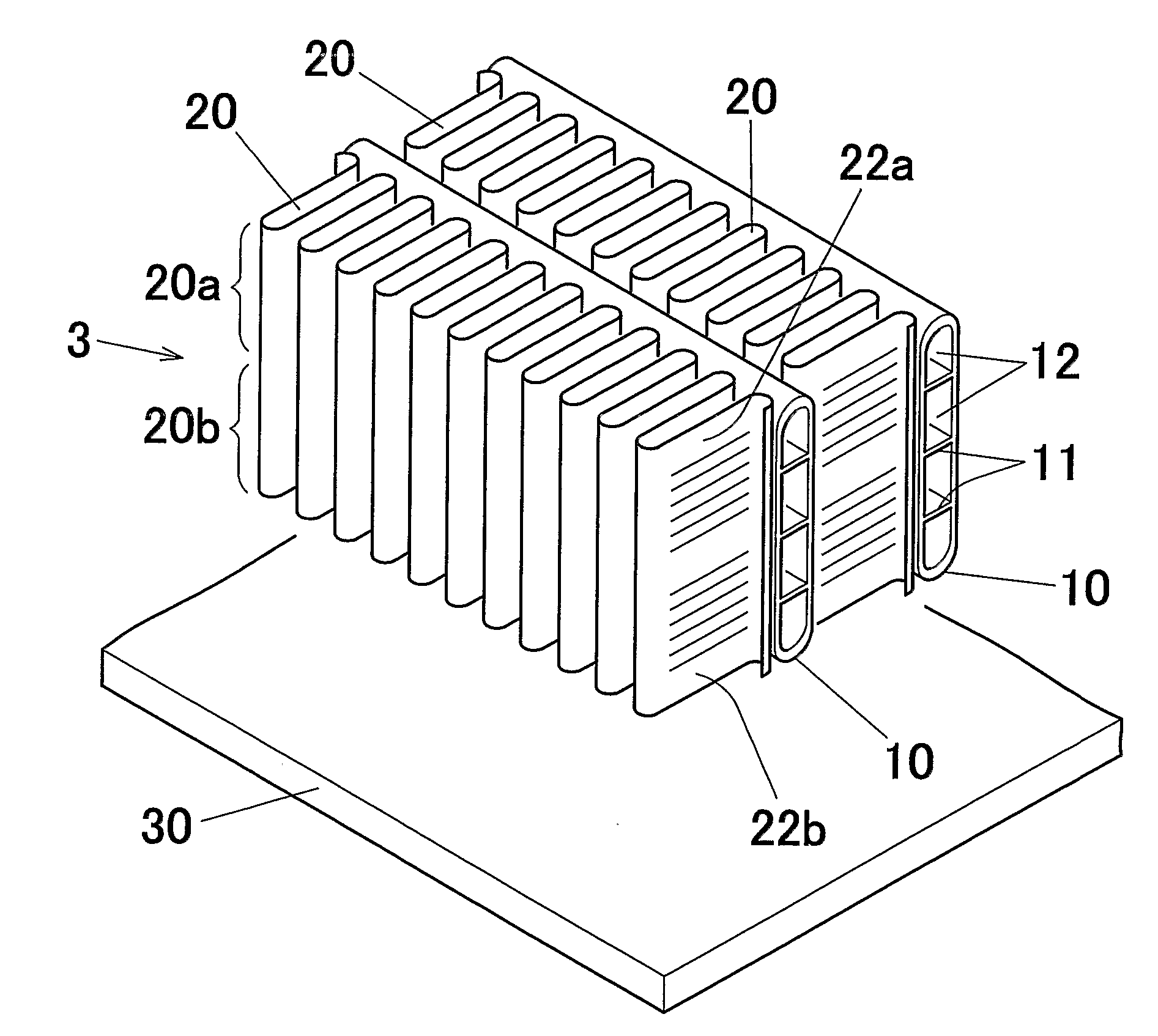
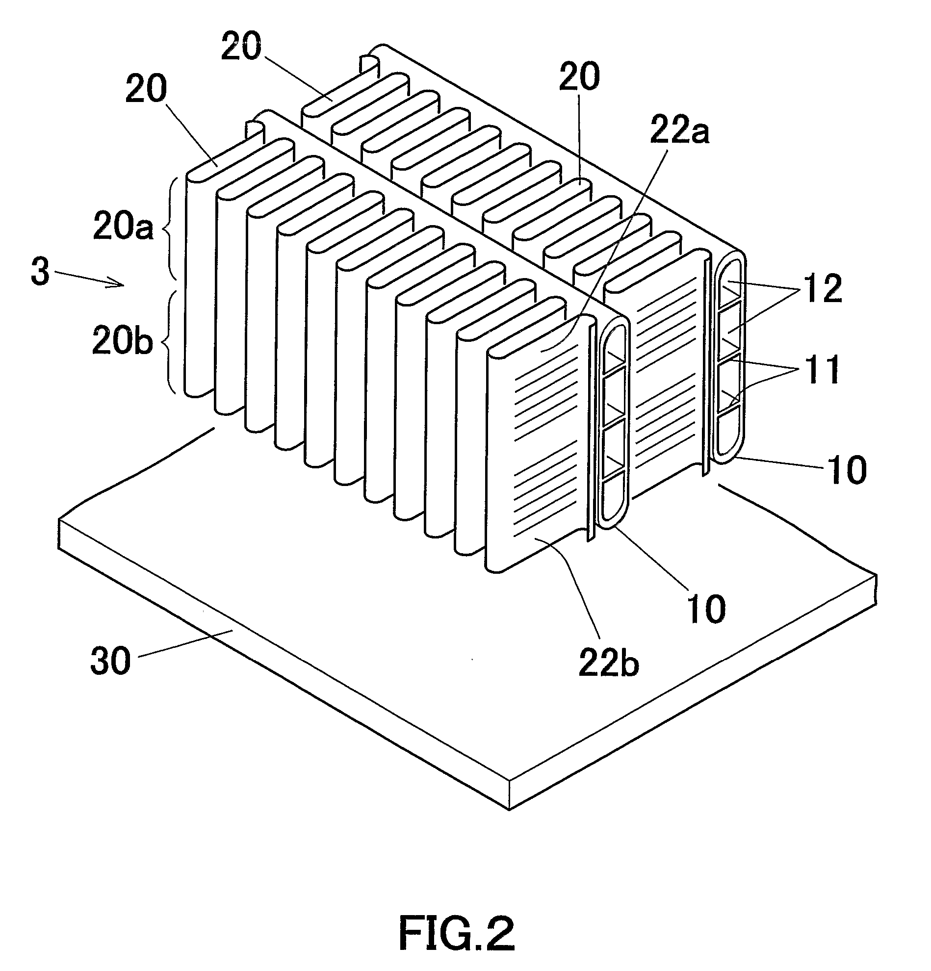
[0088] As shown in FIG. 2, a single fin 20 was disposed between the adjacent tubes 10 and 10 to thereby obtain a provisionally assembled core portion 3.

[0089] KAl4 as flux was applied to the entire provisionally assembled core portion 3 by spraying, and then the core portion 3 was subjected to heating of 600° C.×10 min in a brazing furnace in a state in which an Al-20% Zn alloy plate 30 was disposed 10 mm apart from the one side of the core portion 3. In this heating for brazing, the Zn evaporated from the Al—Zn alloy plate 30 adhered to the fin 20 and then diffused into the fin 20. Since the Zn diffusion amount becomes smaller as the distance from the Al—Zn alloy plate 30 increases, the Zn concentration along the widthwise direction of the Zn diffusion amount became relatively lower at the one side portion 20a of the fin 20 apart from the Al—Zn alloy plate 30 and higher at the other side portion 20b of the fin 20 near the Al—Zn alloy plate 30.

[0090] In Table 1...

examples 3 & 4

[0091] As shown in FIG. 3, two separate fins 21a and 21b were disposed between the adjacent tubes 10 and 10 with a fin distance D of 1.5 mm to obtain a provisionally assembled core portion 3. Then, KAl4 as flux was applied to the entire provisionally assembled core portion 3 by spraying.

[0092] Then, the core portion 3 was subjected to heating of 600° C.×10 min in a brazing furnace in a state in which the Al—Zn alloy plate 30 (shown in FIG. 2) was disposed near the one side fin 21b of the core portion 3 to braze the tube 10 and fins 21a and 21b.

[0093] In brazing the core portion 3, the core material composition of two fins before brazing, the Zn content of Al—Zn alloy plate 30 and the distance from the Al—Zn alloy plate to the core portion were adjusted. As a result, the fin core material compositions of the one side fin 21a and the other side fin 21b, the Zn concentration difference in the compositions after the brazing are shown in Table 1.

example 7

[0094] As shown in FIG. 3, two fins 21a and 21b were disposed between the adjacent tubes 10 and 10 with a fin distance D of 1.5 mm to obtain a provisionally assembled core portion 3.

[0095] Then, KZnF3 as flux was applied only to the other side fin 21b of the provisionally assembled core portion 3 by spraying, and then the provisionally assembled core portion 3 was subjected to heating of 600° C.×10 min in a brazing furnace to braze the tube 10 and fins 21a and 21b.

[0096] During the brazing of the core portion 3, since the Zn evaporation in the other side fin 21b was restrained by the flux applied on the other side fin 21b, the fin core material composition at the one side fin 21a and the other side fin 21b and the Zn concentration difference in the composition after the brazing became as shown in Table 1.


PUM

PropertyMeasurementUnit
pitting potentialaaaaaaaaaa
distanceaaaaaaaaaa
thicknessaaaaaaaaaa

Abstract

In a heat exchanger having a core portion in which aluminum flat tubes and aluminum fins are disposed alternatively and brazed with each other, each fin has one side portion located at one side of the tube and the other side portion located at the other side of the tube. The one side portion of the fin is higher in pitting potential than the other side portion of the fin, and the pitting potential difference between the one side portion of the fin and the other side portion of the fin is 40 to 200 mV. The pitting potential difference can be formed by the Zn concentration difference in the aluminum alloy constituting the fin.

Description

CROSS REFERENCE TO RELATED APPLICATIONS [0001] This application is an application filed under 35 U.S.C. §111(a) claiming the benefit pursuant to 35 U.S.C. §119(e)(1) of the filing date of U.S. Provisional Application No. 60 / 598,539 filed on Aug. 4, 2004, pursuant to 35 U.S.C. §111(b). [0002] This application claims priority to Japanese Patent Application No. 2004-221861 filed on Jul. 29, 2004 and U.S. Provisional Application No. 60 / 598,539 filed on Aug. 4, 2004, the entire disclosures of which are incorporated herein by reference in their entireties.TECHNICAL FIELD [0003] The present invention relates to a heat exchanger to be manufactured by brazing, and more particularly to a heat exchanger capable of demonstrating excellent fin strength even in the case of an occurrence of fin corrosion. It also relates to a method of manufacturing the heat exchanger. [0004] In this disclosure, the wording of “aluminum” is used to include the meaning of aluminum and its alloy. Furthermore, the wo...

Claims


Application Information

Patent Timeline
Patent Type & Authority Applications(United States)
IPC IPC(8): F28F21/08B21D53/02B23K1/00C22C21/00
CPCB23K1/0012F28D1/05391F28D2021/0084Y10T29/4938F28F19/004F28F21/084Y10T29/4935F28F1/128B23K1/00C22C21/00F28F19/00F28F21/08
Inventor MINAMI, KAZUHIKOHASHIMOTO, TAKENORI
Owner SHOWA DENKO KK
Why Eureka
Try Eureka