Apparatus and method for trajectory modulation of an electron beam

a technology of trajectory modulation and electron beam, applied in the field of electron beam devices, can solve the problems of low efficiency, limited gain of these devices, and reduced efficiency, and achieve the effect of reducing the cost of operation and maintenan

Active Publication Date: 2008-02-21
L3 TECH INC
View PDF2 Cites 5 Cited by
  • Summary
  • Abstract
  • Description
  • Claims
  • Application Information

AI Technical Summary

Benefits of technology

[0010]The invention provides an apparatus and method for trajectory modulating an electron beam in ord

Problems solved by technology

However, in the linear region of operation, a significant portion of the DC beam is not converted to RF, which tends to compromise efficiency.
Also, the circuit length required to translate velocity to current modulation is often substantial.
The gain of these devices is limited

Method used


Image

  • Apparatus and method for trajectory modulation of an electron beam
  • Apparatus and method for trajectory modulation of an electron beam
  • Apparatus and method for trajectory modulation of an electron beam

Examples


third embodiment

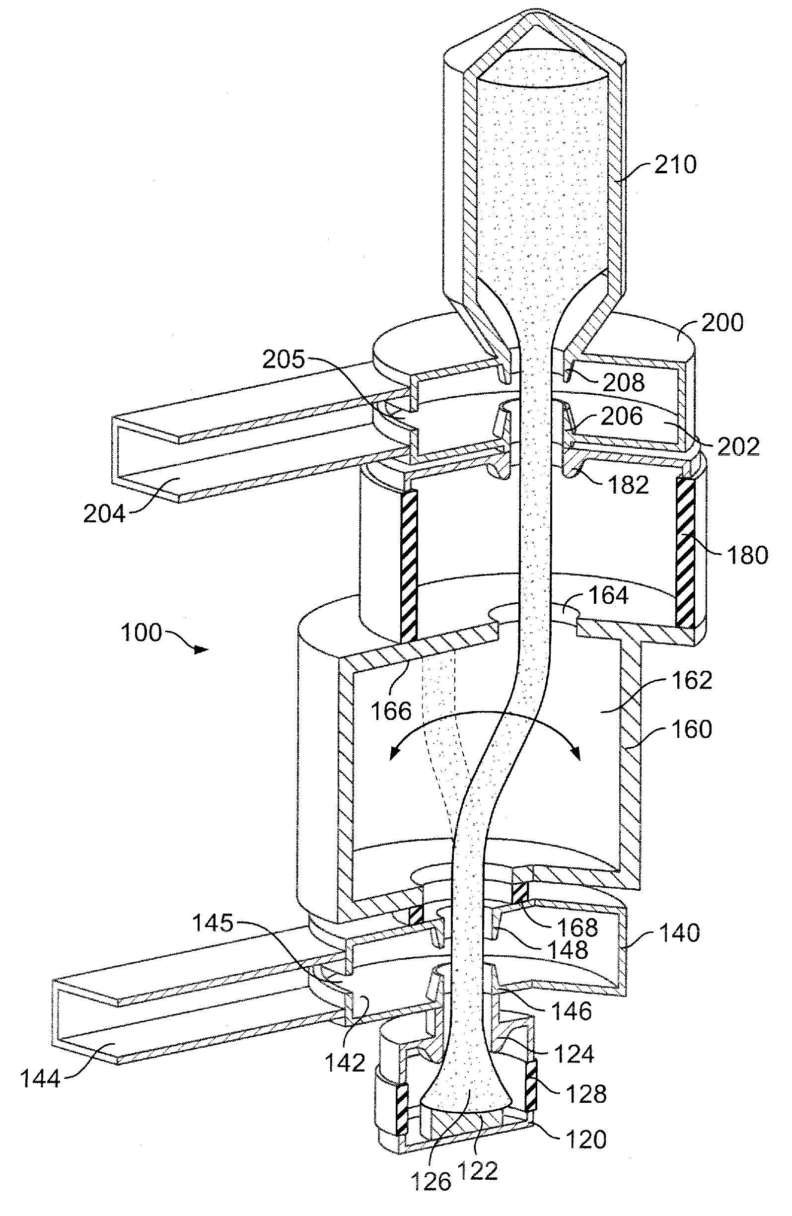
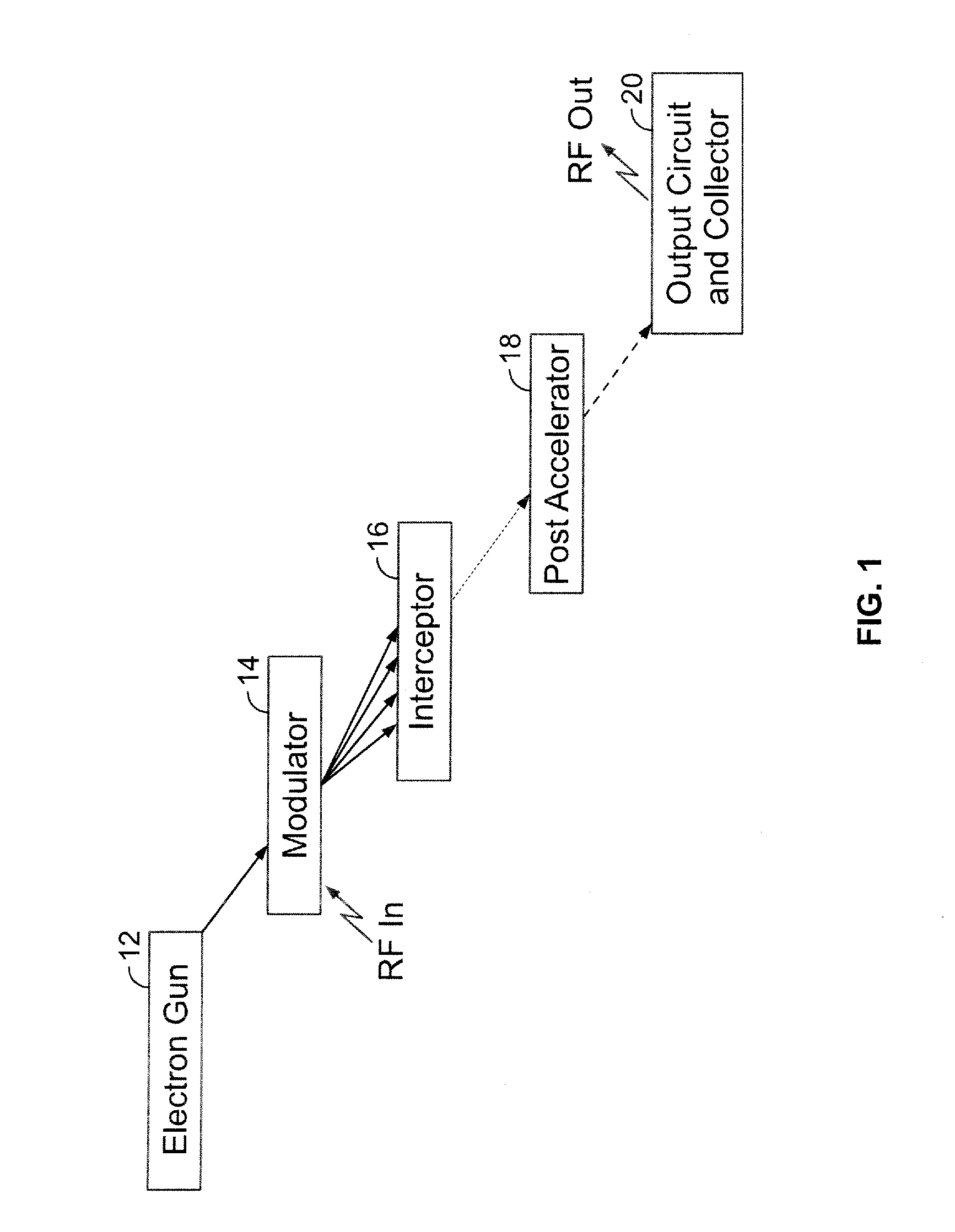
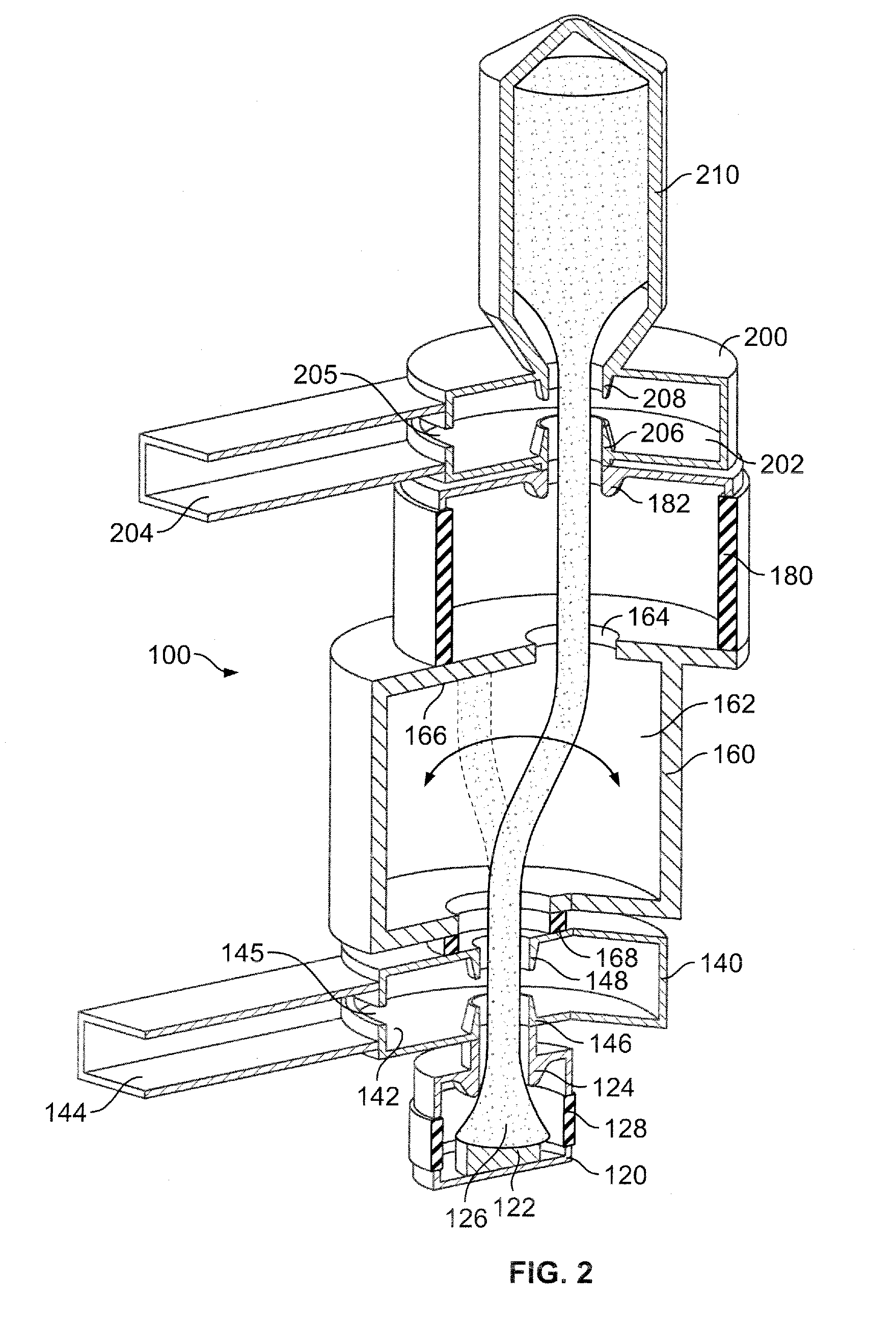
[0036]an exemplary electron device constructed in accordance with the invention is illustrated in FIG. 4. As with the embodiment of FIG. 2, this alternative embodiment of the electron device includes an electron gun 320, a modulator 340, an interceptor 360, an optional post-accelerator 380, an output circuit 390, and a collector 400. Beam transport within the electron device can be facilitated by a magnetic or electrostatic focusing system (not shown), as generally known in the art. The electron device can be configured with any of a variety of beam shapes including annular, sheet and cylindrical, and is also compatible with multiple beam arrangements.

[0037]The electron gun 320 includes an outer cylindrical shell that substantially contains the electron gun components and facilitates mounting of the electron gun within a larger system. Within the outer shell, a cathode structure 322 has a generally cylindrical shape with a cathode emitting surface arranged perpendicularly to a centr...

fourth embodiment

[0043]an exemplary electron device constructed in accordance with the invention is illustrated in FIG. 5. This embodiment allows frequency multiplication without using harmonic interaction. As with the preceding embodiments, this embodiment includes an electron gun 420, a modulator 440, an interceptor 460, an optional post-accelerator 480, an output circuit 490, and a collector 498. Beam transport within the electron device can be facilitated by a magnetic or electrostatic focusing system (not shown), as generally known in the art. The electron device can be configured with a cylindrical or fan-shaped beam although other shapes can be used.

[0044]The electron gun 420 includes an outer cylindrical shell that substantially contains the electron gun components and facilitates mounting of the electron gun within a larger system. Within the outer shell, a cathode structure 422 has a generally cylindrical shape with a cathode emitting surface arranged perpendicularly to a central axis of t...


PUM


Abstract

An electron beam amplification device provides trajectory modulation of an electron beam, and includes an electron gun, a modulator, an interceptor, an output circuit, and a collector. The electron gun produces an electron beam. The modulator receives an RF input signal and provides a corresponding electromagnetic field region that alters trajectory of the electron beam in correspondence with the RF input signal. The interceptor has at least one aperture oriented such that the electron beam transmits through the aperture when the electron beam altered by the modulator follows a particular transmission path and impacts upon the interceptor when the electron beam trajectory altered by the modulator follows a path other than the particular transmission path. The output circuit is arranged so that the electron beam transmitted through the interceptor aperture passes therethrough and produces an RF output signal. The collector recovers remaining energy of the electron beam after passing through the output circuit. An optional post-accelerator may be located between the modulator and the output circuit for increasing energy of the electron beam exiting the interceptor aperture.

Description

RELATED APPLICATION DATA[0001]This application claims priority pursuant to 35 U.S.C. § 119(e) to provisional patent application Ser. No. 60 / 838,580, filed Aug. 17, 2006, the subject matter of which is incorporated by reference herein in its entirety.BACKGROUND OF THE INVENTION[0002]1. Field of the Invention[0003]The present invention relates to electron beam devices, and more particularly, to an electron tube amplifier utilizing trajectory modulation of an electron beam.[0004]2. Description of Related Art[0005]Electron tube amplifiers are well known in the art for converting the energy of an electron beam to microwave energy in response to an RF drive signal. In a typical linear beam electron device, such as a traveling wave tube (TWT) or klystron, an electron beam originating from an electron gun is caused to propagate through an RF interaction structure. At the end of its travel, the electron beam is deposited in a collector that captures the remaining energy of the spent electron...

Claims


Application Information

Patent Timeline
IPC IPC(8): H01J3/26
CPCH01J25/78H01J23/06
Inventor KIRSHNER, MARK FREDERICKWILSEN, CRAIG BISSETKOWALCZYK, RICHARD DONALD
Owner L3 TECH INC
Why Eureka
Try Eureka