Sealing arrangement with a segmented seal and pressure relief

a sealing arrangement and sealing technology, applied in the field of coal gasification, can solve the problems of not revealing a sealing apparatus, and achieve the effect of reducing the pressure differential

Active Publication Date: 2008-02-21
THE BABCOCK & WILCOX CO
View PDF2 Cites 35 Cited by
  • Summary
  • Abstract
  • Description
  • Claims
  • Application Information

AI Technical Summary

Benefits of technology

[0004]It is an object of the present invention to provide a sealing apparatus for use in a pressure vessel for protection of the vessel shell and the back or outside of a conduit member from exposure to high syngas temperature and corrosive gases. The invention accommodates thermal and pressure differentials during operation. Another object of the present invention is to provide a pressure relief means for reducing pressure differential between opposite sides of a conduit member contained within the pressure vessel.
[0013]One problem solved by the present invention is the protection of the pressure vessel from the hot gas that contains corrosive compounds and protection of the heat absorbing pressure part cage (or conduit) from high differential pressures across the cage or between the hot gas volume and the annulus (or cavity) between the cage and the pressure vessel. The combination of the segmented seal ring with resiliently biased pressure and pressure relief doors with resiliently biased pressure responsive relief means is the complete assembly concept that prevents contact of the effluent gas with the inside wall of the pressure vessel, and allows for instantaneous pressure balance between the hot gas volume and the annulus.
[0016]There is a positive seal between the hot gas volume and the annulus between the cage and the pressure vessel, which keeps harmful gasification products away from the pressure vessel for corrosion protection and reduced exposure of high temperature gases on the pressure vessel;

Problems solved by technology

None, however, disclose a sealing apparatus of a segmented ring construction positioned around an outer wall section of a conduit member with resiliently biased pressure device(s) or, pressure relief apparatus with resilient biased pressure for protection of the conduit member from high differential pressures.

Method used


Image

  • Sealing arrangement with a segmented seal and pressure relief
  • Sealing arrangement with a segmented seal and pressure relief
  • Sealing arrangement with a segmented seal and pressure relief

Examples


Embodiment Construction

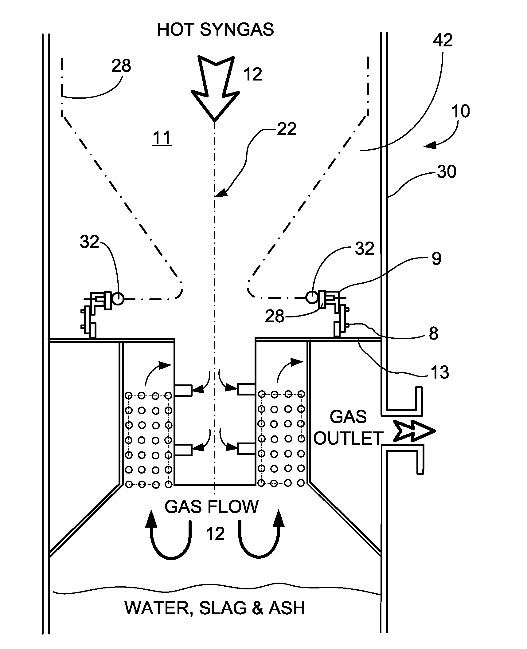
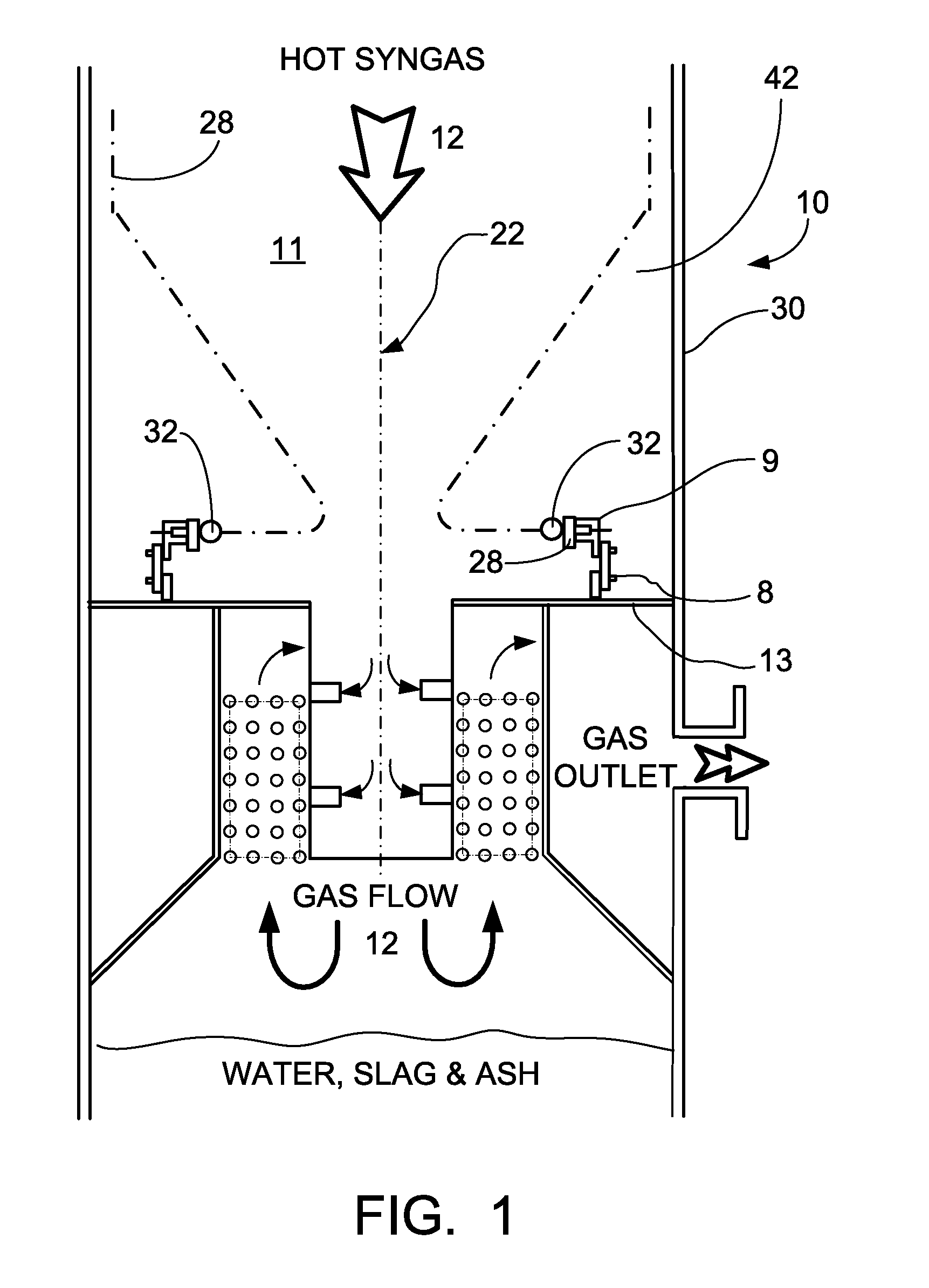
[0028]Referring now to the drawings, in which like reference numerals are used to refer to the same or similar elements, FIG. 1 shows a sealing apparatus 9 and pressure relief apparatus 8 of the present invention operatively installed in a pressure vessel 10 such as a synthesis gas cooler (SGC) 10. The pressure relief apparatus 8is adapted to reduce the pressure difference between opposite sides of a conduit member or cage 28 when a predetermined pressure differential is reached, and the sealing apparatus 9 is adapted to provide a fluid tight seal between a flue 11 defined by the conduit member 28 and an inner cavity 42 located between the conduit member 28 and an outer shell 30 of the SGC. The flue 11, as is shown in FIG. 1, is defined by the conduit member or cage 28, and typically comprises heat exchange elements such as fluid cooled tubes and / or radiant heat transfer surfaces. Synthesis gas or effluent 12 such as that produced by a gasification process is introduced into the flu...


PUM

PropertyMeasurementUnit
pressureaaaaaaaaaa
resilientaaaaaaaaaa
distanceaaaaaaaaaa

Abstract

A sealing apparatus adapted for use in a pressure vessel such as a synthesis gas cooler. The sealing apparatus is of a segmented plate construction formed around an outer wall section of a conduit means of the pressure vessel that defines at least part of a passage for receiving effluent from a gasification process. Pressure responsive mechanisms are provided on the plate segments to maintain the pressure difference across the sealing apparatus within the acceptable operating limits as well as to permit instantaneous pressure release to prevent damage to the pressure part assembly or cage. The seal is also maintained continuously through the differential growth movement between the conduit means and the pressure vessel during heat up and cool down cycles.

Description

FIELD AND BACKGROUND OF THE INVENTION[0001]The present invention relates in general to the field of coal gasification and, in particular, an apparatus for use with certain pressure vessels such as radiant syngas coolers (RSCs) to provide sealing between the hot syngas and the pressure vessel and to provide for instantaneous pressure relief against high differential pressures during transients.[0002]A radiant syngas cooler (RSC) is a component of an integrated gasification combined cycle (IGCC) power plant. A stream of hot syngas and molten ash from the gasification process enters the top of the RSC, a vertical vessel. The RSC recovers heat from the syngas to generate steam, and removes most of the entrained solids. During normal operation, a seal must be maintained to prevent or minimize hot syngas from contacting certain parts of the vessel. During certain conditions, transient operating pressure excursions can occur which must be accommodated or relieved in order to protect condui...

Claims


Application Information

Patent Timeline
Patent Type & Authority Applications(United States)
IPC IPC(8): F16J15/02C10J3/68F16B31/02C10J1/207
CPCC10J3/485C10J3/78C10J2200/09Y02E20/16C10K1/101F16B5/0266Y02E20/18C10J2300/093Y10T137/4259Y10T137/7838Y10T137/7905
Inventor WILSON, RICKEY A.KRAFT, DAVID L.FRY, STEVEN R.
Owner THE BABCOCK & WILCOX CO
Why Eureka
Try Eureka