Optimized modular electrical machine using permanent magnets

Active Publication Date: 2008-02-21
BUTTERFIELD PAUL D
View PDF46 Cites 55 Cited by
  • Summary
  • Abstract
  • Description
  • Claims
  • Application Information

AI Technical Summary

Benefits of technology

[0015]The toroidal conductor assembly has a novel conductor geometry with a continuous arcuate or preferably involute (gear tooth) pattern on each side of each conductor sub-assembly. In a preferred embodiment, the pattern is formed by a wire winding on a grooved and perforated or notched toroidal form. Alternately, the conductor pattern may be formed by a plated or deposited conductive material in a grooved substrate that is finished to preserve insulating b

Problems solved by technology

However, the traditional designs do not optimize other criteria that contribute to the overall efficiency and performance of an electrical machine having a high power-to-weight r

Method used


Image

  • Optimized modular electrical machine using permanent magnets
  • Optimized modular electrical machine using permanent magnets
  • Optimized modular electrical machine using permanent magnets

Examples


Embodiment Construction

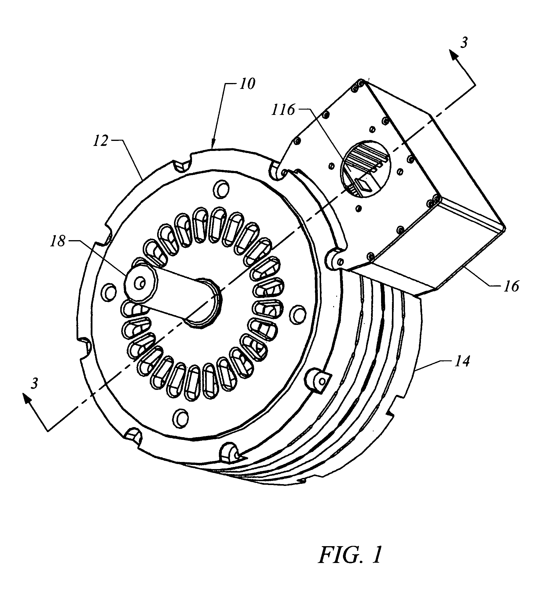
[0033]A preferred embodiment of the electrical machine of this invention is shown in FIG. 1, and is designated generally by the reference numeral 10. The electrical machine 10 has an outer housing 12 with a main body 14 and a side mounted electronics compartment 16. On the central axis of the electrical machine 10 is a projecting rotor shaft 18. In the embodiment of FIG. 1, the electrical machine 10 is operational as a brushless motor or generator and is suitable as a motor-generator for electric vehicles.

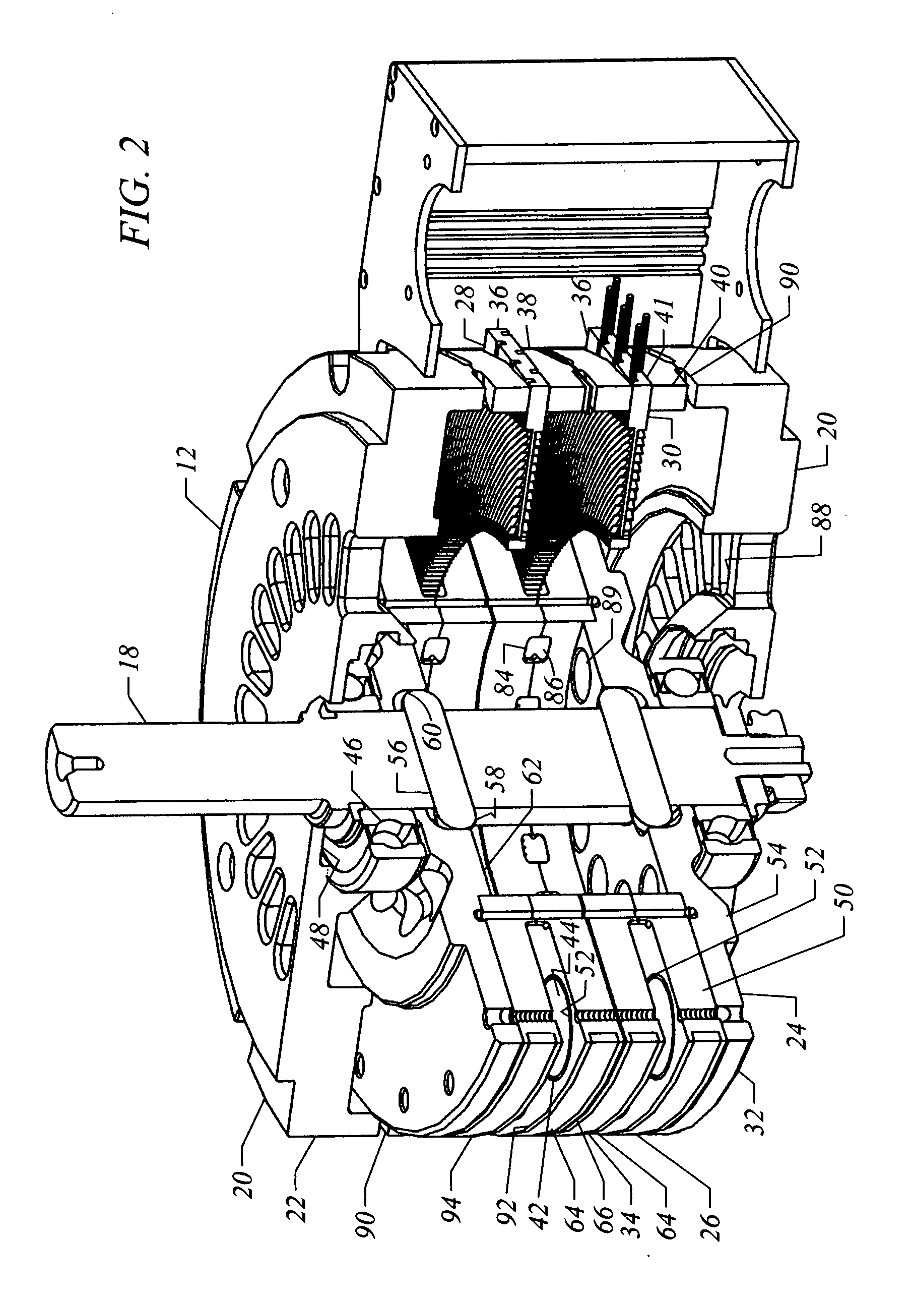
[0034]Referring in addition to the compound, cross-sectional perspective of FIG. 2, the outer housing 12 is formed with two end plates 20 with peripheral side walls 22 that encase a rotor 24 with magnet assembly 26 and a stator 28 with a conductor assembly 30. It is to be understood that the preferred electrical machine 10 of this invention is an axial flux machine that may have multiple modules to vary the power with similar and preferably identical components. In the embodiment o...


PUM


Abstract

An electrical machine having a magnet assembly with a magnet carrier ring with an even number of permanent magnets mounted in the carrier ring around a circular locus, and a conductor assembly with one or more conductor circuits wound in a double helix wave winding around a flat conductor support ring with the conductor circuits having uniformly curved conductor segments of involute or arcuate configuration wherein the magnet assembly and conductor assembly are contained in a housing with the magnet assembly rotating relative to the conductor assembly.

Description

BACKGROUND OF THE INVENTION[0001]This invention relates to electrical machines using permanent magnets and in particular to axial field motor / generators that are robust and include design features for high efficiency in generating energy or developing torque. The optimized modular design allows the electrical machine to be versatile and incorporated in a variety of applications from transportation and power generation to machinery and robotics.[0002]Axial field electrical machines differ from drum type machines by the ability to stack a series of similar modules along an axis to achieve multiple levels of power generation or torque development. In a typical module of an axial field electrical machine, a magnet assembly has two sub-assemblies that are spaced apart to create an axial flux gap in which a disk-like conductor assembly is centrally positioned. Movement of the conductor assembly relative to the magnet assembly induces a current in the conductor or conductors that in part m...

Claims


Application Information

Patent Timeline
IPC IPC(8): H02K21/12H02K1/22
CPCH02K1/2793H02K3/26H02K3/28H02K3/47H02K21/24H02K5/225H02K11/0073H02K11/048H02K13/08H02K5/20H02K11/33H02K5/207H02K1/2795H02K11/00
Inventor BUTTERFIELD, PAUL
Owner BUTTERFIELD PAUL D
Why Eureka
Try Eureka