Eureka AIR delivers breakthrough ideas for toughest innovation challenges, trusted by R&D personnel around the world.

Automatic laser alignment system

Inactive Publication Date: 2008-02-21
GRIMM JIMM +2
View PDF2 Cites 26 Cited by
  • Summary
  • Abstract
  • Description
  • Claims
  • Application Information

AI Technical Summary

Benefits of technology

[0002] Linear accelerators, X-Ray simulators and other equipment for radiation oncology typically have a gantry that can rotate about a focal point called the isocenter. At any gantry angle the radiation beam points through the isocenter. Typically there is a laser on each wall perpendicular to the axis of rotation of the gantry, and another laser on the ceiling directly above the isocenter, and some clinics also have a laser on the wall facing the gantry. The laser beams should all pass through the isocenter, to assist in positioning the patient and other treatment devices.
[0006] Accurate radiation therapy treatment requires that the laser alignment of both the diagnostic imaging equipment and the linear accelerator are extremely accurate. If some of the lasers for the linear accelerator happened to be misaligned by a couple millimeters and the corresponding lasers for the diagnostic imaging equipment happened to be misaligned by a couple millimeters in the opposite direction, the combined error could be nearly half a centimeter. The presently disclosed invention could reduce this error to tenths of millimeters, and it would be far more convenient to use than the existing manual alignment procedure.

Problems solved by technology

Unfortunately, aligning the lasers to the isocenter is still a tedious and inaccurate manual process.
This is a tedious manual process.
In normal sized treatment rooms, it is hard for the clinical user to see the target at the isocenter clearly when they are standing way over at the wall adjusting the lasers.
It often takes several iterations and the final result could still be misaligned by more than one millimeter.
The ceiling lasers are even more inconvenient to adjust.
The critical issue is that the laser beams must all intersect as close to the chosen model isocenter as possible.
If some of the lasers for the linear accelerator happened to be misaligned by a couple millimeters and the corresponding lasers for the diagnostic imaging equipment happened to be misaligned by a couple millimeters in the opposite direction, the combined error could be nearly half a centimeter.

Method used


Image

  • Automatic laser alignment system
  • Automatic laser alignment system
  • Automatic laser alignment system

Examples


Embodiment Construction

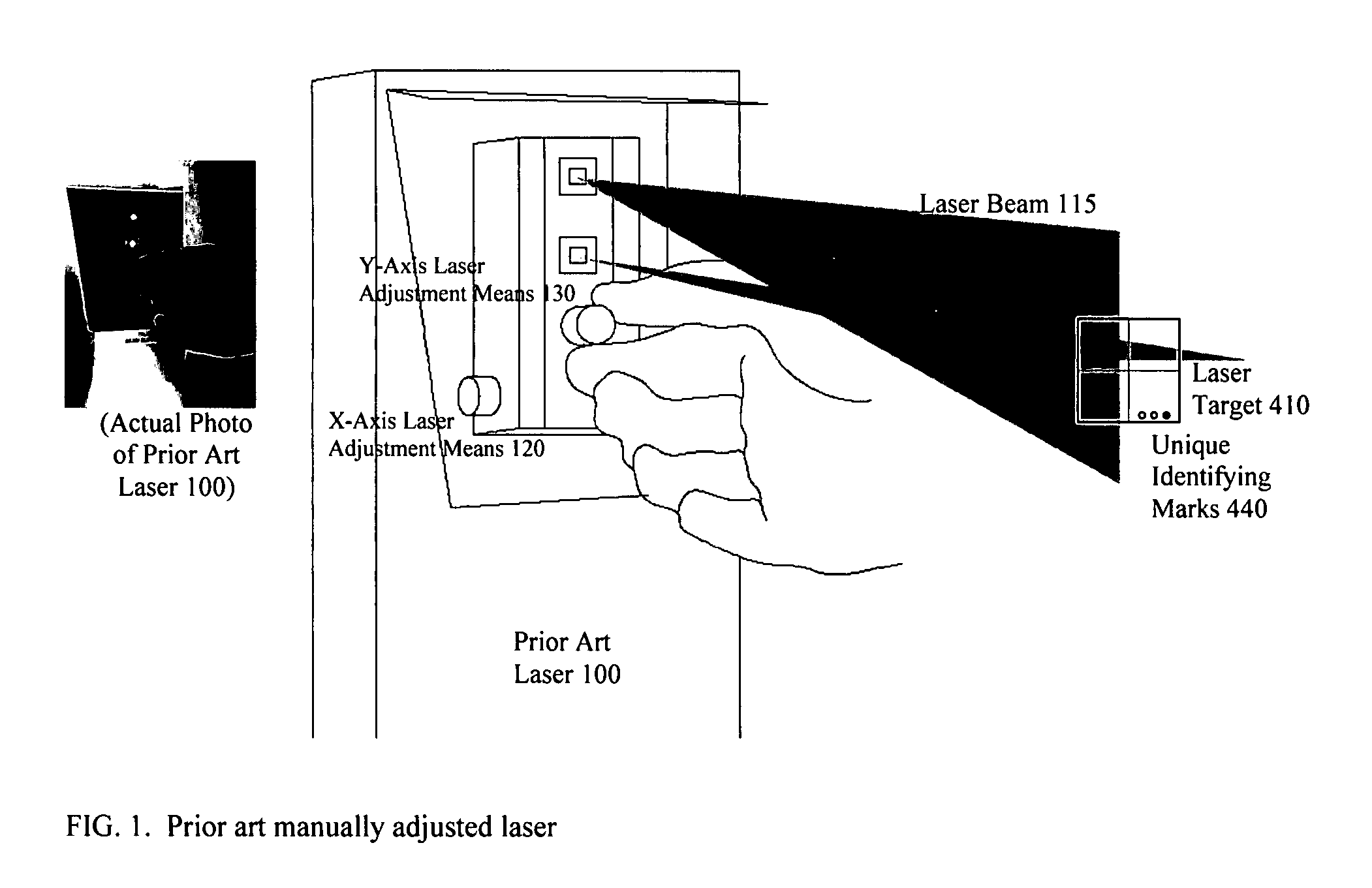
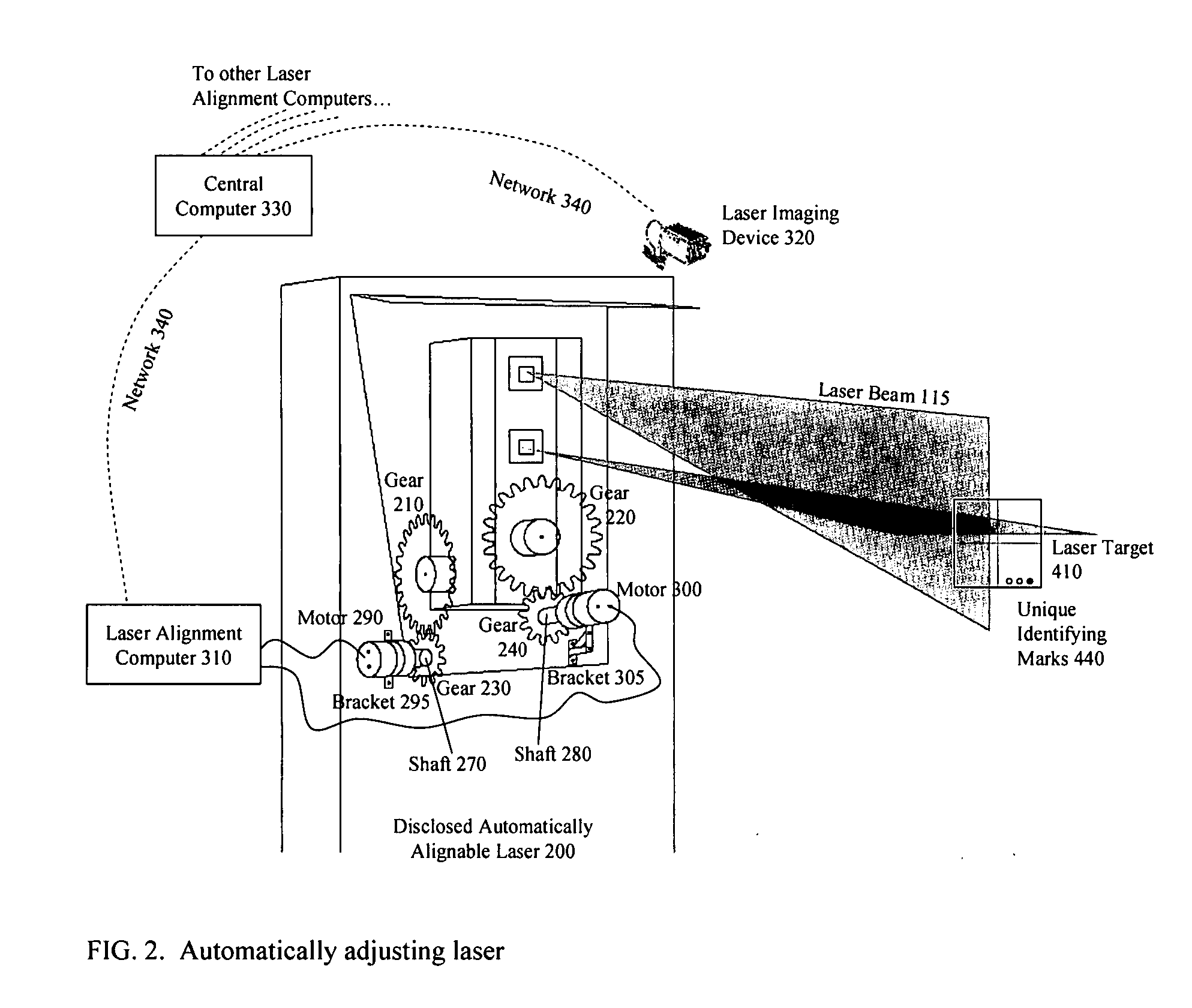
[0019] A prior art manually alignable laser 100 is shown in FIG. 1. The laser beam 115 is emitted from the laser 100, and the X-Axis manual adjustment means 120 can align the laser beam 115 positive or negative in the X direction, and the Y-Axis manual adjustment means 130 can align the laser beam 115 positive or negative in the Y direction. There are many other varieties of prior art lasers with different kinds of knobs, screws, motors, or other means to realign the laser beam 115. The present invention applies to any prior art laser that has means for the user to align the laser beam in two orthogonal dimensions. X and Y coordinates are relative to the laser target 410. This manual alignment process is tedious and subject to potentially large errors, so an automated system with better accuracy is very desirable. In the automatic system, the manual adjustment means 120 and 130 will be replaced with a connection to automatic adjustment means, such as motors, hydraulics, or any other...


PUM


Abstract

A device that automatically aligns laser beams to corresponding targets to establish a frame of reference for radiation oncology or diagnostic imaging. The device is comprised of one or more lasers and corresponding laser alignment targets, two motors for each laser to control its direction, a laser imaging device or devices, a wireline or wireless network, a computer for controlling each laser's motors, and a central computer connected to the laser imaging device(s). Each laser alignment target has crosshairs to align the laser beam to, and each laser alignment target also has unique identifying marks to distinguish it from the other lasers' targets. Each laser has two means for automatic alignment, one to adjust the laser beam positive or negative along X coordinates, and another to adjust the laser beam positive or negative along Y coordinates. The laser imaging device(s) is used to measure how accurately the laser beam is aligned, and the images are fed to the central computer which calculates the laser alignment error for each laser, and sends feedback across the network to each laser's alignment computer. The computer for each laser uses the error feedback to control the laser's automatic alignment means so as to minimize the alignment error.

Description

FIELD OF THE INVENTION [0001] The invention relates to laser alignment systems that are used as a frame of reference for positioning patients and quality assurance equipment in radiation oncology and diagnostic imaging. The invention is an automated system to conveniently and accurately align the lasers. BACKGROUND AND SUMMARY OF THE INVENTION [0002] Linear accelerators, X-Ray simulators and other equipment for radiation oncology typically have a gantry that can rotate about a focal point called the isocenter. At any gantry angle the radiation beam points through the isocenter. Typically there is a laser on each wall perpendicular to the axis of rotation of the gantry, and another laser on the ceiling directly above the isocenter, and some clinics also have a laser on the wall facing the gantry. The laser beams should all pass through the isocenter, to assist in positioning the patient and other treatment devices. [0003] Diagnostic imaging equipment such as X-Ray simulators, CT scan...

Claims


Application Information

Patent Timeline
IPC IPC(8): G01B11/00
CPCG01B11/27
Inventor GRIMM, JIMMGRIMM, CHRISTOPHERGRIMM, JAMES
Owner GRIMM JIMM
Why Eureka
Eureka Blog
Learn More