Complex architecture for dispersing heat

a technology of complex architecture and heat dissipation, applied in the direction of cooling/ventilation/heating modifications, thin material processing, semiconductor/solid-state device details, etc., can solve the problems of high production cost, difficult to meet the requirements of thin, light and short, and get heavy weight, etc., to achieve excellent dissipation efficiency, reduce production cost, and lighten weight

Inactive Publication Date: 2008-02-21
HORNG CHIN FU
View PDF3 Cites 2 Cited by
  • Summary
  • Abstract
  • Description
  • Claims
  • Application Information

AI Technical Summary

Benefits of technology

[0008]The primary object of the invention is therefore to specify a complex architecture for dispersing heat, which can transmit and dissipate heat to all regi

Problems solved by technology

A conventional heat sink of big volume, made by copper or aluminum, occupies large space, gets heavy weight and has high production cost, obviously it is difficult to meet the requirements of thin, light and short.
Although graphite materials are of conductivity, the heat c

Method used


Image

  • Complex architecture for dispersing heat
  • Complex architecture for dispersing heat
  • Complex architecture for dispersing heat

Examples


first embodiment

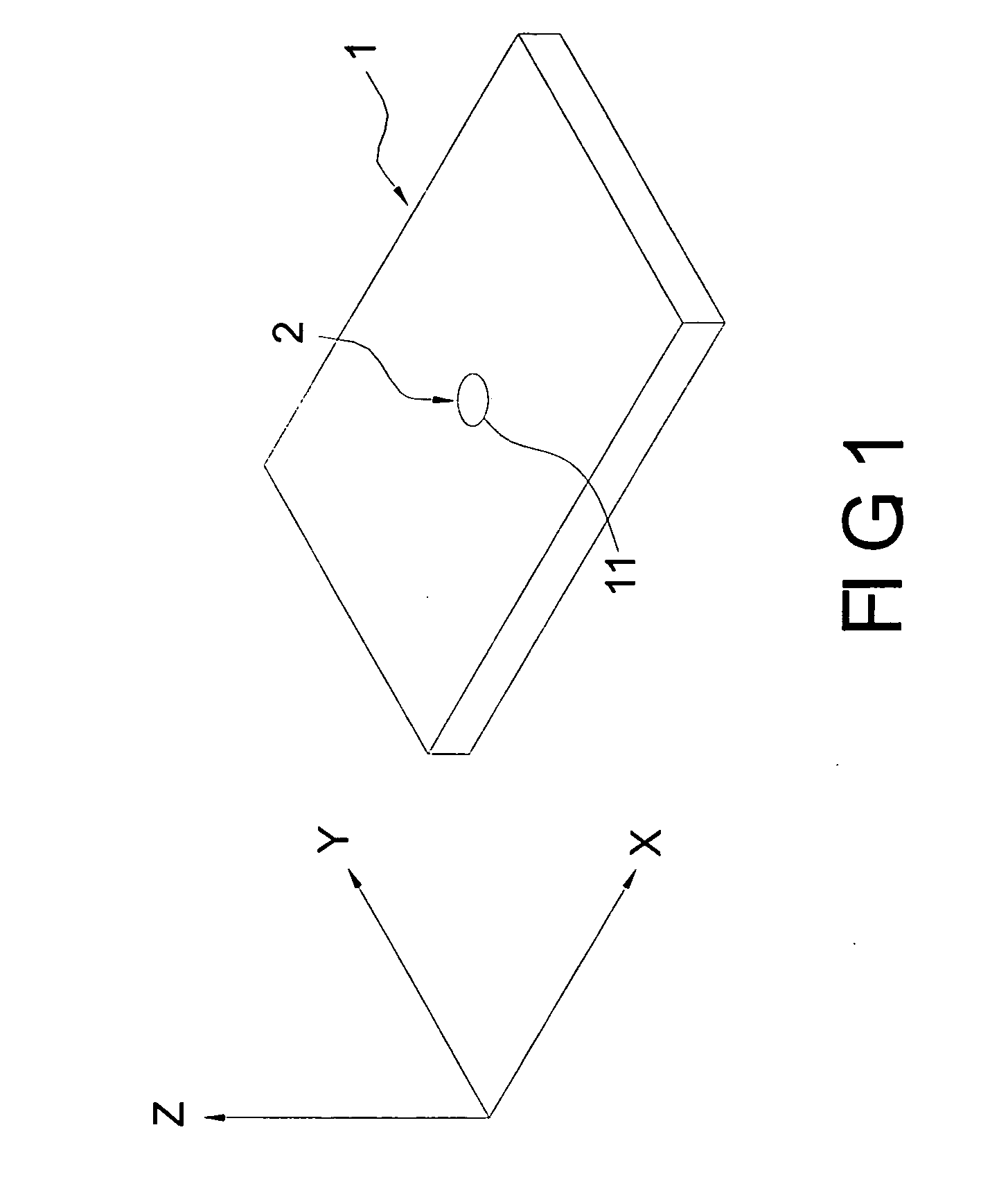
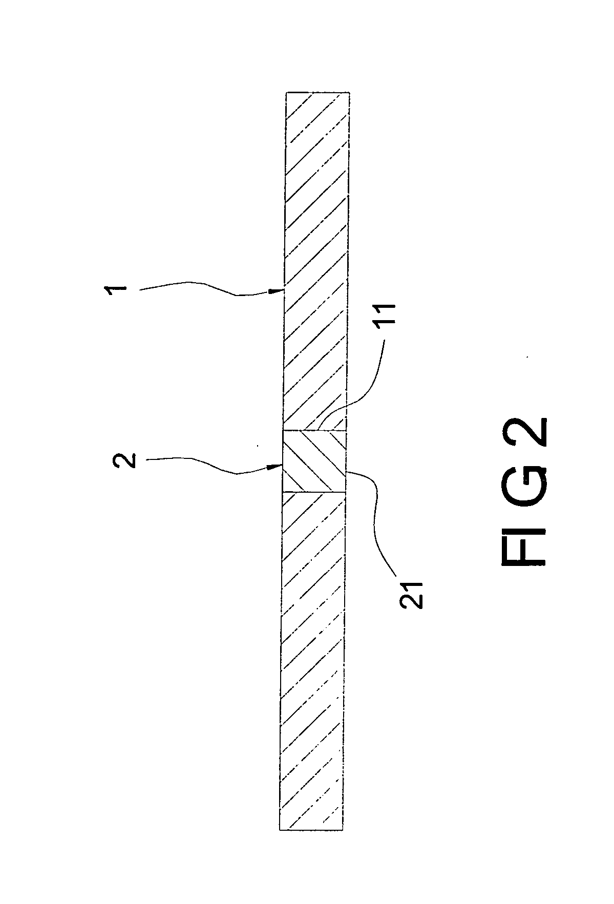
[0022]The metal device 2 is of good heat conductivity, such as a copper or aluminum element, and mating with the reception cavity 11 of the graphite device 1. In the first embodiment, the metal device is round for relating to reception cavity 11. The metal device 2 is disposed in the reception cavity 11 fixedly, such as tightly fitting in the reception cavity 11 or bonding to the reception cavity 11 via a heat conductivity medium. The metal device 2 includes a contact portion 21 formed at an end (a bottom end) thereof. The contact portion 21 is exposed out of the bottom surface of the graphite device 1 in order to connect with one kind of heat sources. By these elements mentioned above, the complex architecture for dispersing heat is accomplished.

[0023]Referring to FIGS. 1 and 3, the complex architecture can be arranged on a heat source 5, such as a central process unit. The contact portion 21 of metal device 2 connects with the heat source 5. There could be a heat conductivity adhe...

second embodiment

[0024]the present invention illustrated in FIG. 4, the metal device 2 can be rectangular for relating to the corresponding reception cavity 11.

third embodiment

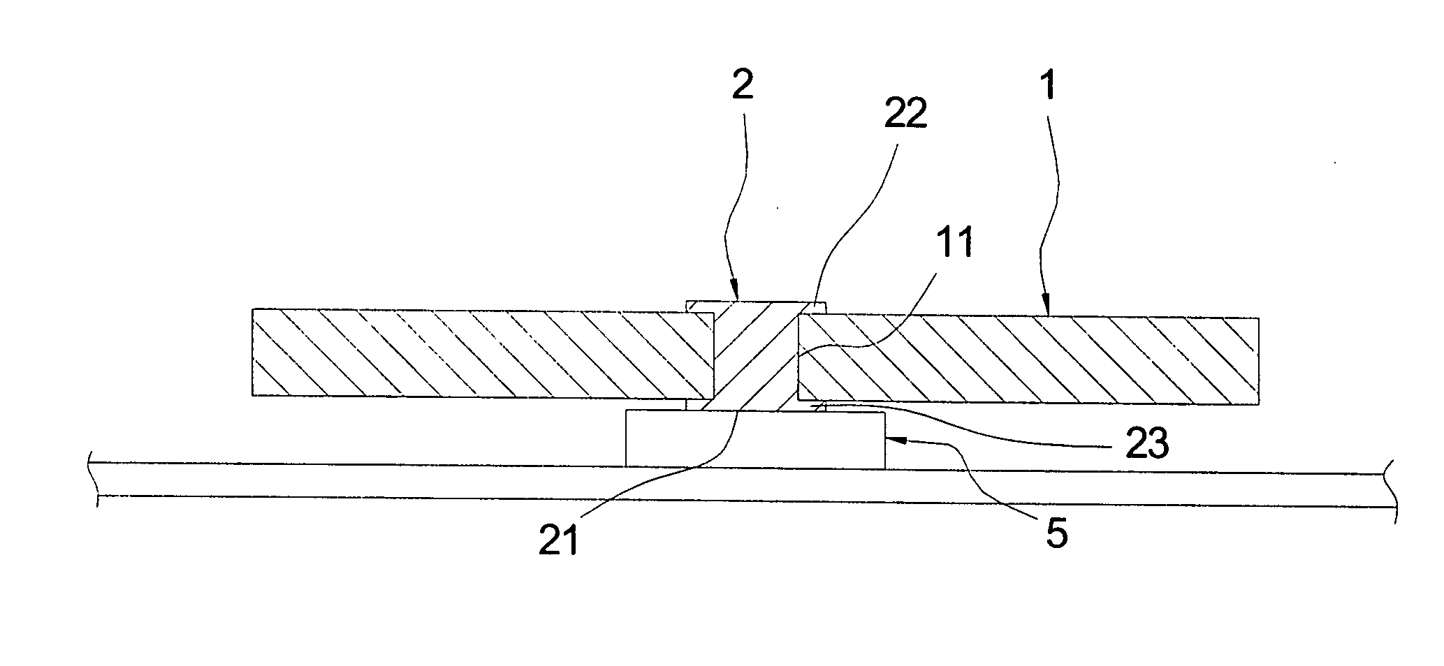
[0025]the present invention illustrated in FIG. 5, the metal device 2 includes two head portions 22, 23 at two opposite ends thereof for retaining against top and bottom surfaces of the graphite device 1 respectively.


PUM


Abstract

A kind of the complex architecture for dispersing heat includes one graphite device and one metal device with heat conductibility. The metal device, such as copper or aluminum, combines with the graphite device. The metal device transmits heat to the normal direction, and then transmits heat to the horizontal direction by graphite. This design of the complex architecture can transmit and dissipate heat to all regions of the graphite device so that its dissipation efficiency is better.

Description

BACKGROUND OF THE INVENTION[0001]1. Field of the Invention[0002]The present invention relates to a complex architecture for dispersing heat, and particularly relates to a complex architecture arranged on a heat source for dispersing heat and gaining good dissipation efficiency.[0003]2. Background of the Invention[0004]As the rapid development of the computer technology grows, heat sources, such as central process units, generate more and more heat. Further due to the trendy minimization size, the arisen dense heat should be dissipated out of the system into exterior environment in order to permit the heat source works n in the appropriate temperature. Usually, a heat sink with large contact area is provided to the heat source for transmitting and dispersing the arisen heat.[0005]A conventional heat sink of big volume, made by copper or aluminum, occupies large space, gets heavy weight and has high production cost, obviously it is difficult to meet the requirements of thin, light and...

Claims


Application Information

Patent Timeline
IPC IPC(8): B32B3/10
CPCH01L23/3677H01L23/373Y10T428/24331H01L2924/0002H01L2924/00H05K7/20
Inventor HORNG, CHIN-FU
Owner HORNG CHIN FU
Why Eureka
Try Eureka