Fuel Cell System

Inactive Publication Date: 2008-02-21
TOYOTA IND CORP +1
View PDF5 Cites 17 Cited by
  • Summary
  • Abstract
  • Description
  • Claims
  • Application Information

AI Technical Summary

Benefits of technology

[0021] In the fuel cell system, it is preferred that the fuel cell system be installed in a fuel cell driven automobile. T

Problems solved by technology

For such reasons, when, for example, the ambient temperature is below zero degrees Celsius, the temperature of the hydrogen supplied to the hydrogen electrode decreases and causes water existing on the hydrogen reaction surface of the fuel cell to freeze.

Method used


Image

  • Fuel Cell System
  • Fuel Cell System
  • Fuel Cell System

Examples


first embodiment

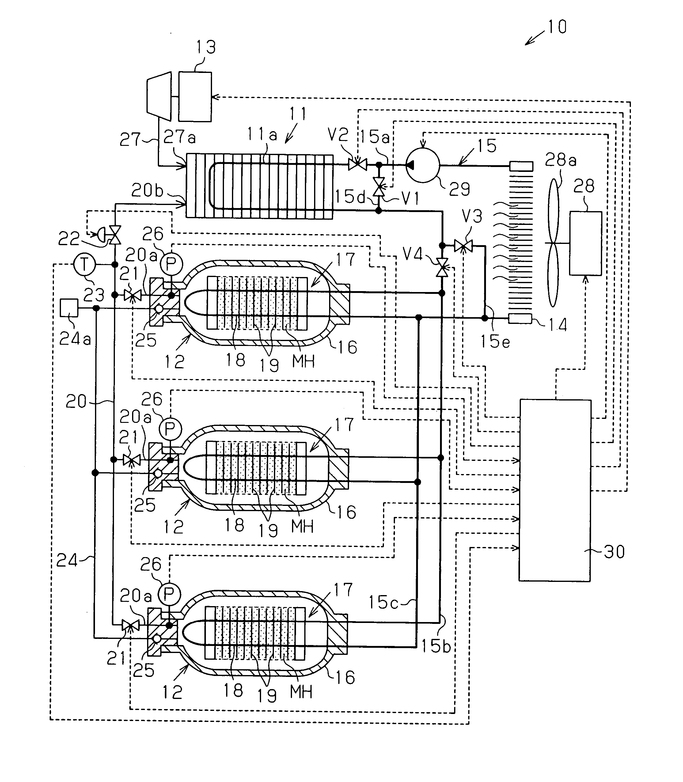
[0027] A fuel cell system 10 according to a first embodiment of the present invention will now be described with reference to FIG. 1.

[0028] The fuel cell system 10 includes a fuel cell 11, three hydrogen storage tanks 12, a compressor 13, and a radiator 14. The fuel cell 11, the hydrogen storage tanks 12, and the radiator 14 are connected to one another by a heat medium passage 15. In the present embodiment, a long life coolant (LLC) is used as a heat medium that flows through the heat medium passage 15.

[0029] The fuel cell 11 is a solid polymer fuel cell. The fuel cell 11 generates direct-current electric energy (direct-current power) by causing hydrogen supplied from each hydrogen storage tank 12 to react with oxygen contained in the air supplied from the compressor 13. The fuel cell 11 includes a heat exchanger 11a for cooling the fuel cell 11 during operation. In the present embodiment, the heat exchanger 11a forms part of the heat medium passage 15.

[0030] Each hydrogen stora...

second embodiment

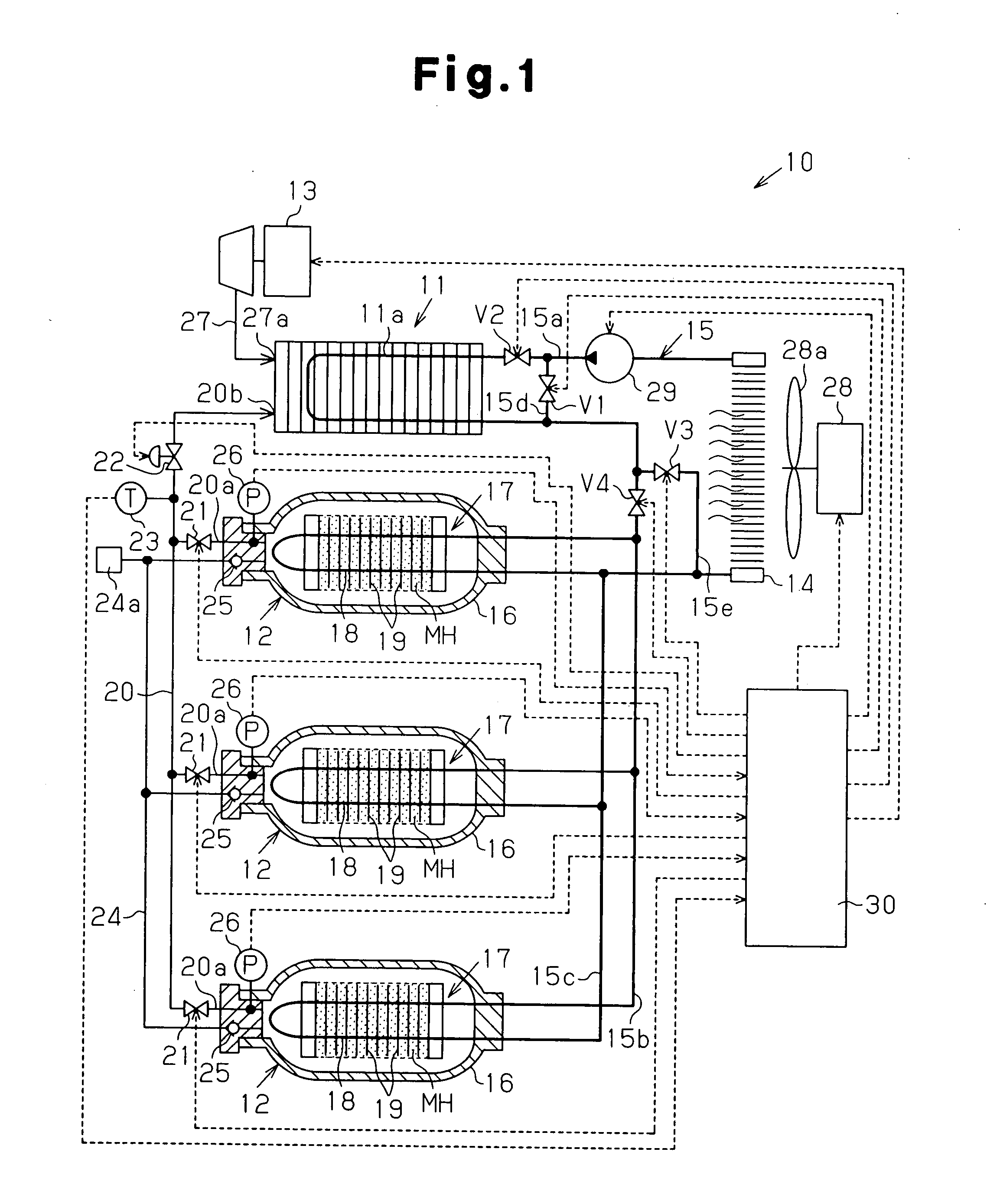
[0059] A fuel cell system 10 according to a second embodiment of the present invention will now be described with reference to FIG. 2. The components in the second embodiment that are the same as in the first embodiment will not be described in detail.

[0060] As shown in FIG. 2, each hydrogen storage tank 12 has a hydrogen inlet and a hydrogen outlet respectively arranged at opposite ends 12a and 12b of a tank main body 16. Each hydrogen storage tank 12 has a heat medium inlet and a heat medium outlet and the hydrogen outlet both arranged at the end 12a of the tank main body 16. A pipe 20 is connected to the hydrogen outlet side end 12a of each hydrogen storage tank 12 by a connection portion 20a. A pressure sensor 26 is arranged in each connection portion 20a to detect the pressure in the corresponding hydrogen storage tank 12.

[0061] In the hydrogen storage tanks 12 of the first embodiment, the heat medium heats the vicinity of the hydrogen outlet at the end 12a after the heat med...

third embodiment

[0065] A fuel cell system 10 according to a third embodiment of the present invention will now be described with reference to FIG. 3. The components in the third embodiment that are the same as in the first and second embodiments will not be described in detail.

[0066] A heat medium passage 15 has a sixth portion 15f connecting an outlet of a heat exchanger 11a and an inlet of a radiator 14 instead of the second portion 15b in the first embodiment. A heat exchanger 18 in each hydrogen storage tank 12 has an inlet connected to a seventh portion 15g that branches from the sixth portion 15f. An electromagnetic three-way valve 31, which functions as a switching means, is arranged at each portion branching from the sixth portion 15f to the seventh portions 15g. Further, the heat exchanger 18 of each hydrogen storage tank 12 has an outlet connected to an eighth portion 15h that branches from the sixth portion 15f. Each electromagnetic three-way valve 31 is connected to a controller 30 and...


PUM


Abstract

In a fuel cell system 10, hydrogen is supplied to a fuel cell 11 from a hydrogen storage tank 12 provided with a hydrogen-absorbing alloy MH and a heat exchanger 18. In this process, the pressure in the hydrogen storage tank 12 is held at a level equal to or higher than a predetermined pressure by using a heat medium that cooled the fuel cell 11. When the temperature of the hydrogen supplied to the fuel cell 11 is at the predetermined temperature or below, a control device 30 controls, based on a detection signal provided from a temperature sensor 23, first to fourth electromagnetic valves V1 to V4 so that the heat medium after having cooled the fuel cell 11 is supplied to the heat exchanger 18.

Description

TECHNICAL FIELD [0001] The present invention relates to a fuel cell system, and more particularly, to a fuel cell system in which hydrogen is supplied from a hydrogen storage tank containing a hydrogen storage member to a fuel cell, a heat medium used to cool the fuel cell and to heat the hydrogen storage member, with pressure in the tank maintained to be greater than or equal to the pressure necessary to supply hydrogen to the fuel cell. BACKGROUND ART [0002] With enhanced awareness of global warming prevention in recent years, to reduce carbon dioxide emissions from vehicles, electric vehicles using fuel cell systems and home power supplies fuel cell systems have been developed. In such a fuel cell system, hydrogen is supplied as a fuel gas from a hydrogen storage tank to a fuel cell. [0003] A hydrogen storage alloy, which stores hydrogen as a hydride under a certain temperature and pressure conditions and releases hydrogen under different temperature and pressure conditions, has ...

Claims


Application Information

Patent Timeline
IPC IPC(8): H01M8/04F17C11/00F17C7/00H01M8/10H01M8/00
CPCF17C2221/012H01M8/04007H01M8/04014H01M8/04089H01M8/04208Y02E60/50H01M8/04253H01M2250/20Y02E60/321Y02T90/32H01M8/04216Y02E60/32Y02T90/40
Inventor KUBO, HIDEHITOMORI, DAIGORO
Owner TOYOTA IND CORP
Why Eureka
Try Eureka