Method and system of determining nibp target inflation pressure using an sp02 plethysmograph signal

a plethysmograph signal and inflation pressure technology, applied in the field of automated blood pressure measurement apparatus, can solve the problems of extended measurement time and patient discomfort, and achieve the effect of improving the performance of a non-invasive blood pressure monitor

Inactive Publication Date: 2008-02-21
GENERAL ELECTRIC CO
View PDF43 Cites 40 Cited by
  • Summary
  • Abstract
  • Description
  • Claims
  • Application Information

AI Technical Summary

Benefits of technology

[0006]The following describes a method and system for monitoring the blood pressure in a patient that utilizes the output of a pulse monitor, such as the SpO2 plethysmograph waveform from an SpO2 monitor, to improve the performance of a non-invasive blood pressure (NIBP) monitor. The NIBP monitor includes a blood pressure cuff that is placed upon the limb of a patient, such as the arm. The blood pressure cuff is selectively inflated and deflated by a central processor, which controls the availability of pressurized air to the cuff and the position of valves that release air from the cuff. During the deflation of the blood pressure cuff from an initial inflation pressure, oscillation pulses are detected and the central processor calculates a pulse amplitude for each oscillation pulse, such that the pulse amplitudes are utilized to calculate the blood pressure of a patient.

Problems solved by technology

If the initial inflation pressure is selected well above the systolic blood pressure for the patient, the NIBP system over inflates the blood pressure cuff, resulting in patient discomfort and extended measurement time.

Method used


Image

  • Method and system of determining nibp target inflation pressure using an sp02 plethysmograph signal
  • Method and system of determining nibp target inflation pressure using an sp02 plethysmograph signal
  • Method and system of determining nibp target inflation pressure using an sp02 plethysmograph signal

Examples


Embodiment Construction

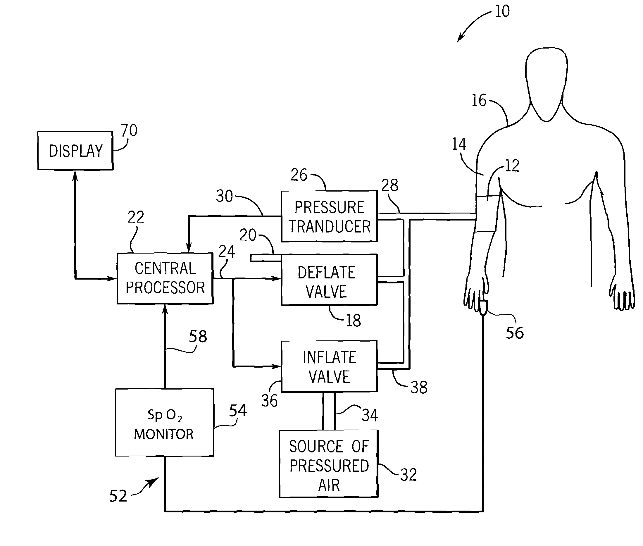
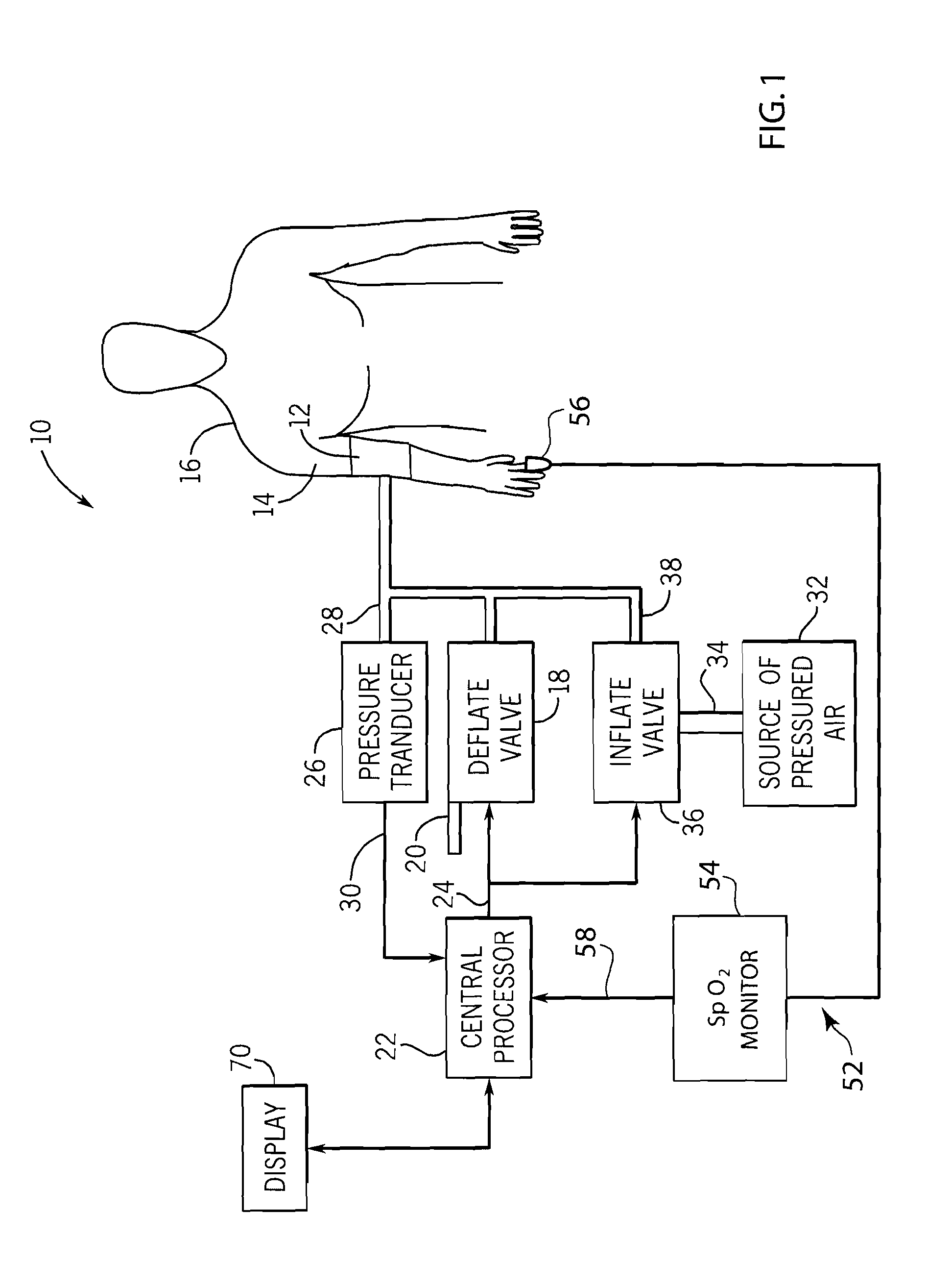
[0017]FIG. 1 generally illustrates a non-invasive blood pressure (NIBP) monitoring system 10 of conventional construction. The NIBP monitoring system 10 includes a blood pressure cuff 12 placed on the arm 14 of a patient 16. The blood pressure cuff 12 can be inflated and deflated for occluding the brachial artery of the patient 16 when in the fully inflated condition. As the blood pressure cuff 12 is deflated using the deflate valve 18 having exhaust 20, the arterial occlusion is gradually relieved. The deflation of the blood pressure cuff 12 by the deflate valve 18 is controlled by a central processor 22 through the control line 24.

[0018]A pressure transducer 26 is coupled by duct 28 to the blood pressure cuff 12 for sensing the pressure within the cuff 12. In accordance with conventional oscillometric techniques, the pressure transducer 26 is used to sense pressure oscillations in the cuff 12 that are generated by pressure changes in the brachial artery under the cuff. The electri...


PUM


Abstract

A method and system for operating a non-invasive blood pressure monitor that utilizes an SpO2 plethysmograph signal to determine the initial inflation pressure for the blood pressure cuff of the NIBP monitor. A pulse sensor is placed on the patient's limb distal to the blood pressure cuff such that as the blood pressure cuff is inflated, the pulse signals from the pulse sensor will be reduced. When the blood pressure cuff reaches systolic pressure, the pulse signals from the pulse sensor will be initially attenuated and eventually eliminated, thus providing an indication that the cuff pressure has reached systolic pressure for the patient. The central processor of the NIBP monitor compares the pulse signals during cuff inflation to an average pulse signal and terminates the inflation of the blood pressure cuff upon sufficient attenuation. The use of the SpO2 plethysmograph signal to determine the initial inflation pressure reduces both the over-inflation of the blood pressure cuff and the under-inflation of the blood pressure cuff which increases the rate at which the blood pressure measurement can be made while increasing patient comfort.

Description

FIELD OF THE INVENTION[0001]The present invention relates to a method of operating an automated blood pressure measuring apparatus. More specifically, the present invention relates to a method of operating an automated non-invasive blood pressure (NIBP) monitor that utilizes a separate pulse monitor to enhance the performance of the NIBP monitor.BACKGROUND OF THE INVENTION[0002]Automated blood pressure monitoring has rapidly become an accepted and, in many cases, essential aspect of human healthcare. Such monitors are now a conventional part of the patient environment in emergency rooms, intensive and critical care units, and in the operating theater.[0003]The oscillometric method of measuring blood pressure involves applying an inflatable cuff around an extremity of a patient's body, such as a patient's upper arm. The cuff is inflated to a pressure above the patient's systolic pressure and then the cuff pressure is reduced either continuously or incrementally in a series of small s...

Claims


Application Information

Patent Timeline
Patent Type & Authority Applications(United States)
IPC IPC(8): A61B5/02
CPCA61B5/02141A61B5/02255A61B5/02225
Inventor FRIEDMAN, BRUCE A.BOOTH, JOHN W.HERSH, LAWRENCE T.
Owner GENERAL ELECTRIC CO
Why Eureka
Try Eureka