Current sensor

a current sensor and current sensor technology, applied in the field of current sensors, can solve the problems of reducing the accuracy of the output signal of the hall effect element, the inability of the current sensor to accurately measure an electric current, and the relatively difficult assembly of the conventional current sensor, etc., to achieve accurate detection of electric current, easy assembly, and accurate measurement of electric curren

Inactive Publication Date: 2008-02-28
DENSO CORP
View PDF7 Cites 33 Cited by
  • Summary
  • Abstract
  • Description
  • Claims
  • Application Information

AI Technical Summary

Benefits of technology

[0006]In view of the above-described problem, it is an object of the present invention to provide a current sensor that accurately measures an electric current and assembles easily.
[0007]A current sensor for measuring an electric current flowing through a conductor includes a ring shaped magnetic core, a bare semiconductor chip, and a case. The magnetic core having a gap and surrounds the conductor. When the electric current flows through the conductor, a magnetic field generated by the electric current is concentrated by the magnetic core and appears in the gap. The bare semiconductor chip has a front surface and a vertical Hall effect element formed on the front surface. The bare semiconductor chip is arranged in the gap of the magnetic core to detect the magnetic field in the gap. The case includes a case body, a case cover, and a conductive terminal. The case body has an inner room for holding the magnetic core and the bare semiconductor chip. The case cover is attached to the case body to seal the inner room. The conductive terminal is supported in the case body. The conductive terminal has a first end exposed to the inner room and electrically connected to the bare semiconductor chip by a bonding wire and a second end exposed to outside the case body to be connectable to an external device. A back surface of the bare semiconductor chip is fixed to the inner room of the case body in such a manner that the front surface of the bare semiconductor chip is parallel to a direction of the magnetic field generated by the electric current flowing through the conductor.
[0008]The bare semiconductor chip having the vertical Hall effect element is not encapsulated with a molding material. Therefore, the vertical Hall effect element can avoid stress from the molding material so that the current sensor can accurately detect the electric current.
[0009]The bare semiconductor chip uses a vertical Hall effect element instead of a conventional lateral Hall effect element. In such an approach, the bare semiconductor chip can be arranged parallel to the direction of the magnetic field in the gap of the magnetic core. Thus, the bare semiconductor chip can be easily connected to the conductive terminal by wire bonding.

Problems solved by technology

The stress causes a reduction in accuracy of an output signal of the Hall effect element.
Accordingly, the conventional current sensor cannot accurately measure an electric current.
In short, the conventional current sensor is relatively difficult to assemble.

Method used


Image

  • Current sensor
  • Current sensor
  • Current sensor

Examples


Embodiment Construction

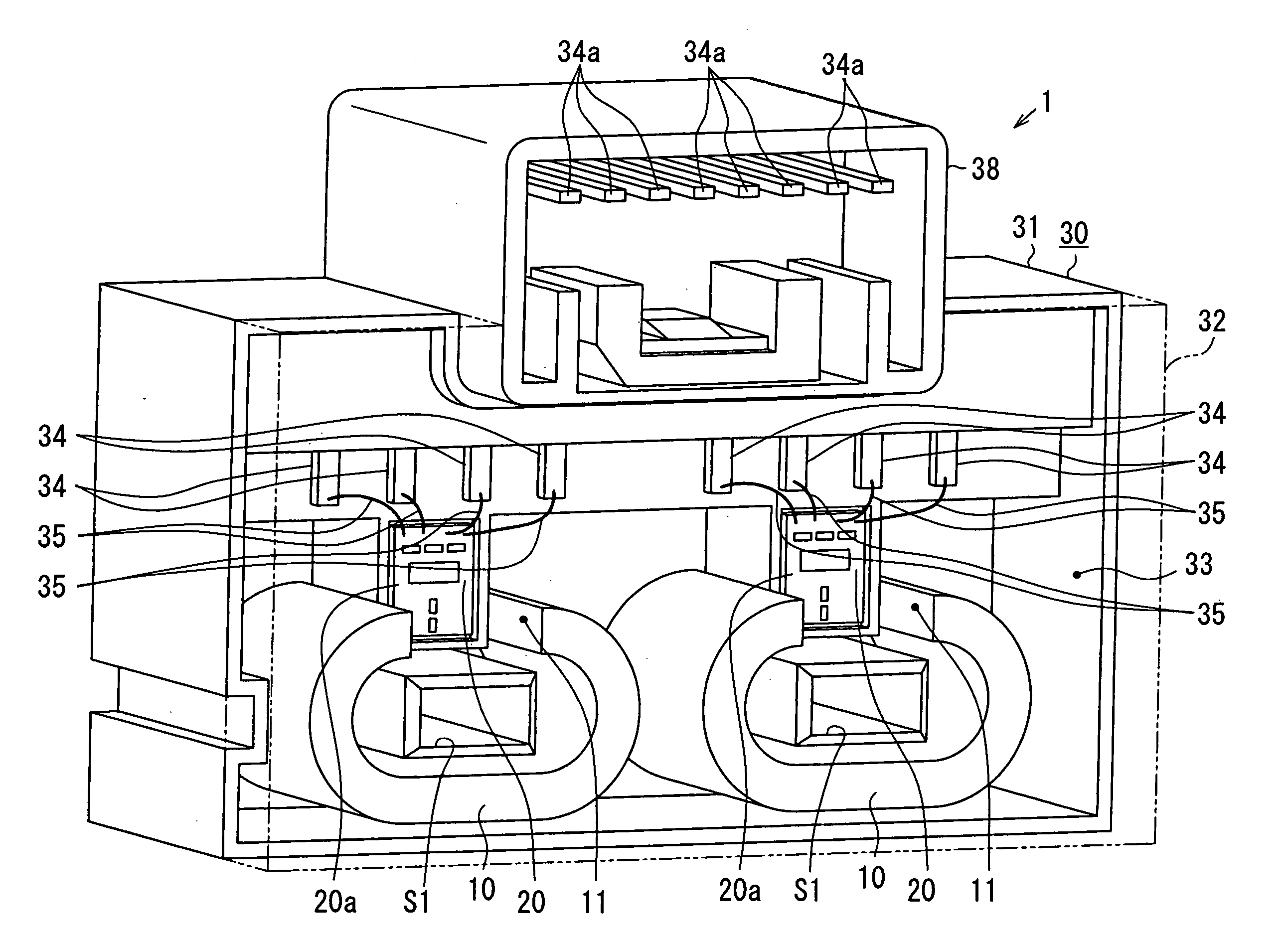
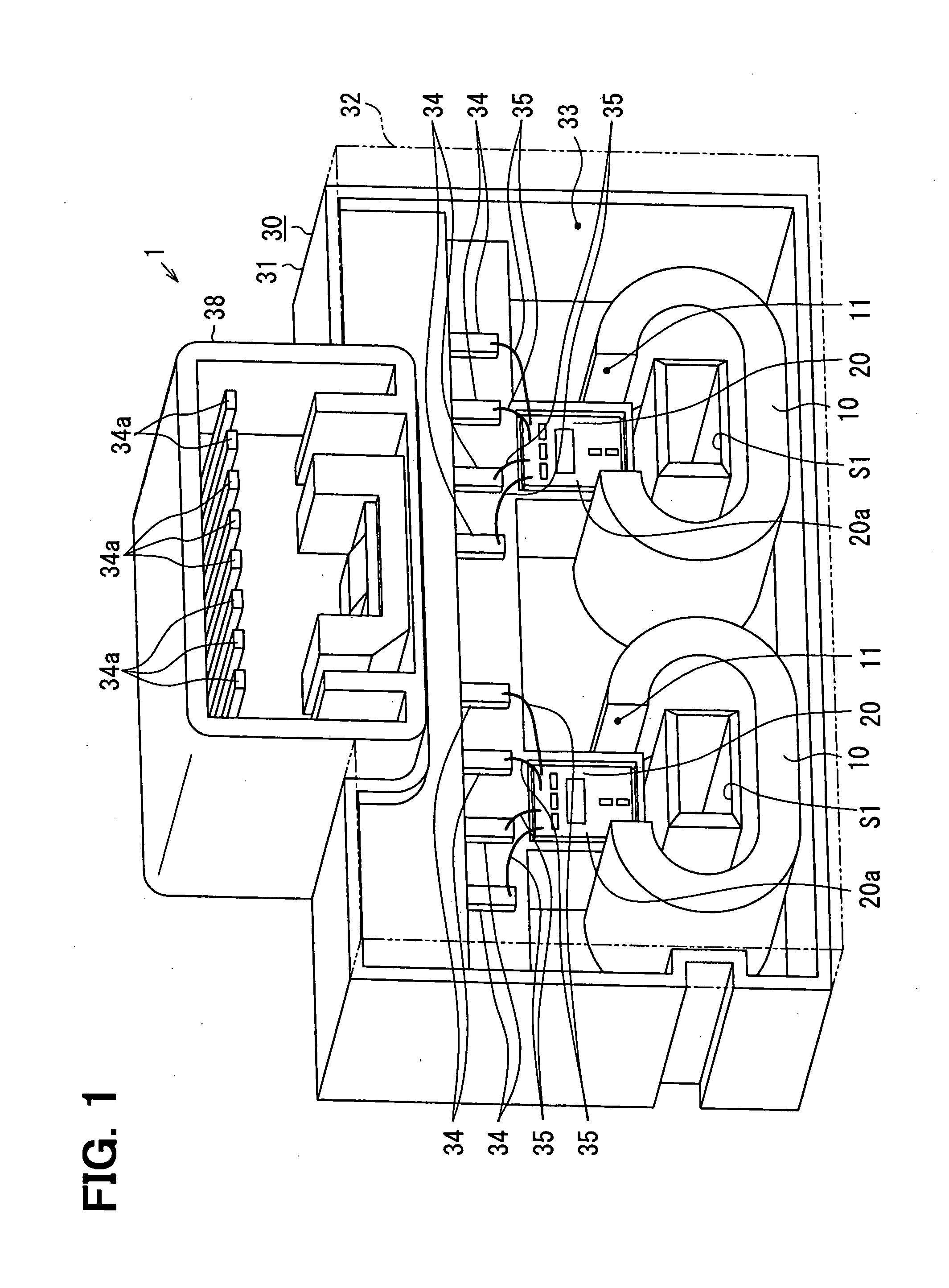
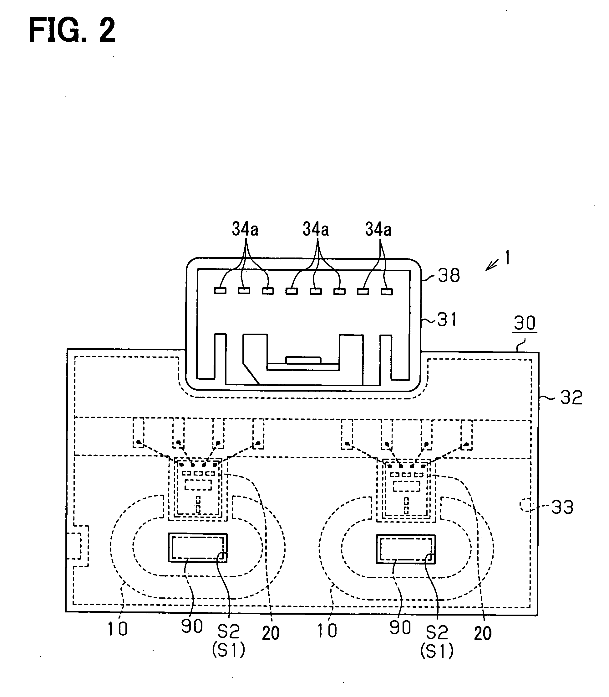
[0022]As shown in FIG. 1, a current sensor 1 according to an embodiment of the present invention includes two sensor sets and a case 30. Each sensor set has a ring-shaped magnetic core 10 and a sensor chip 20. Each sensor set measures an electric current IF flowing through a different conductor 90. For example, each conductor 90 is connected to a different one of three outputs of an inverter (not shown) that drives a three-phase alternating-current (AC) motor for a hybrid electric vehicle (HEV) or an electric vehicle (EV). Thus, the current sensor 1 measures two of three output currents of the inverter at a time.

[0023]The magnetic core 10 and the sensor chip 20 are accommodated in the case 30. The magnetic core 10 has a gap 11 and a center opening. The magnetic core 10 may be, for example, made of a nickel iron magnetic alloy, i.e., permalloy. Specifically, the magnetic core 10 is formed by laminating multiple ring-shaped plates, each of which is made of permalloy and has a thicknes...


PUM


Abstract

A current sensor for measuring an electric current flowing through a conductor includes a ring shaped magnetic core, a bare semiconductor chip, and a case. The magnetic core has a gap and surrounds the conductor. The bare semiconductor chip has a front surface and a vertical Hall effect element formed on the front surface. The bare semiconductor chip is arranged in the gap of the magnetic core to detect a magnetic field generated by the electric current. The magnetic core and the bare semiconductor chip are accommodated in the case. A back surface of the bare semiconductor chip is fixed in the case in such a manner that the front surface of the bare semiconductor chip is parallel to a direction of the magnetic field.

Description

CROSS REFERENCE TO RELATED APPLICATION[0001]This application is based on and incorporates herein by reference Japanese Patent Application No. 2006-229477 filed on Aug. 25, 2006.FIELD OF THE INVENTION[0002]The present invention relates to a current sensor.BACKGROUND OF THE INVENTION[0003]A current sensor has been proposed that measures an electric current by using a Hall effect integrated circuit (IC) made of a semiconductor material such as silicon (Si), indium arsenide (InAs), indium antimonide (InSb), or gallium arsenide (GaAs). Nowadays, a Hall effect IC, in particular, made of silicon is provided as a molded IC chip package. Specifically, as shown in FIGS. 10A-10C, a sensor chip 101 mounted on a lead frame 100 is encapsulated in a molding resin 102 so that a sensor package 103 is provided.[0004]A current sensor disclosed, for example, in U.S. Pat. No. 7,084,617 corresponding to JP 2005-308526 and JP 2005-308527 uses the sensor package 103. As shown in FIG. 11, the conventional c...

Claims


Application Information

Patent Timeline
Patent Type & Authority Applications(United States)
IPC IPC(8): G01R19/15G01R33/07
CPCG01R15/202G01R33/077G01R33/07
Inventor ARATANI, MASAHIROISHIHARA, MASATOOOTAKE, SEIICHIROU
Owner DENSO CORP
Why Eureka
Try Eureka