Pixel circuit

a pixel circuit and circuit technology, applied in the field of pixel circuits, can solve the problems of increasing power consumption, reducing gate voltage, and reducing brightness, and achieve the effects of reducing drive current, excellent brightness uniformity, and large parasitic capacitan

Inactive Publication Date: 2008-02-28
SONY CORP
View PDF0 Cites 36 Cited by
  • Summary
  • Abstract
  • Description
  • Claims
  • Application Information

AI Technical Summary

Benefits of technology

[0019]According to the embodiment of the present invention, a switching transistor making up negative feedback means connects the current path end (e.g., drain) of the drive transistor to the connection point (hereinafter may be called “input side node”) between the current path end of the sampling transistor and the capacitor, after the sampling of the video signal. The operation of this switching transistor negatively feeds an output current flowing through the drive transistor back to the input side node, thus causing a change in the potential. The input side node and the gate of the drive transistor are coupled in an AC fashion by the capacitor. As a result, the gate voltage of the drive transistor changes. The change of the input side node causes the absolute value of the gate voltage Vgs of the drive transistor to decline. The larger the drive transistor output current, the more conspicuous this function becomes. Therefore, if there is a difference in driving capability of the drive transistor (i.e., mobility μ) between pixels, a drive current is caused to decrease. This allows for correction of variations in the mobility μ of the drive transistor, thus providing an image display apparatus with an excellent brightness uniformity.
[0020]In particula

Problems solved by technology

However, negative feedback inevitably results in the reduction of the gate voltage (signal voltage) of the drive transistor, which in turn will lead to a decline in brightness if no countermeasure is taken.
This, however, gives rise to increased power consumption.
However, setting the mobility correction period too short, or of the order of μs, will lead to variations in the timing control due, for example, to wiring delay, thus making it difficult to perform mobility correction operation in a stable manner.
In particular, if the panel is large, wiring

Method used


Image

  • Pixel circuit
  • Pixel circuit
  • Pixel circuit

Examples


Embodiment Construction

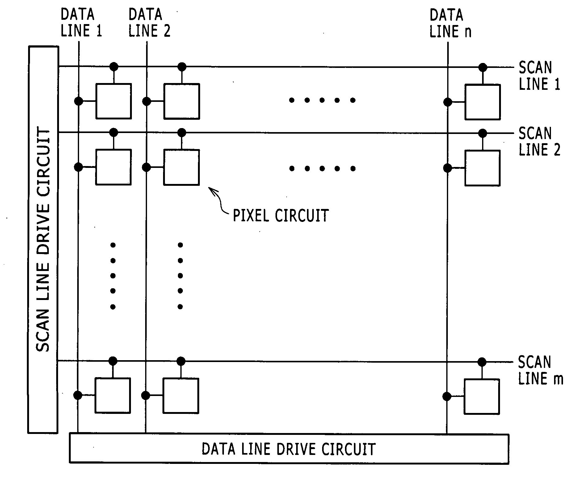
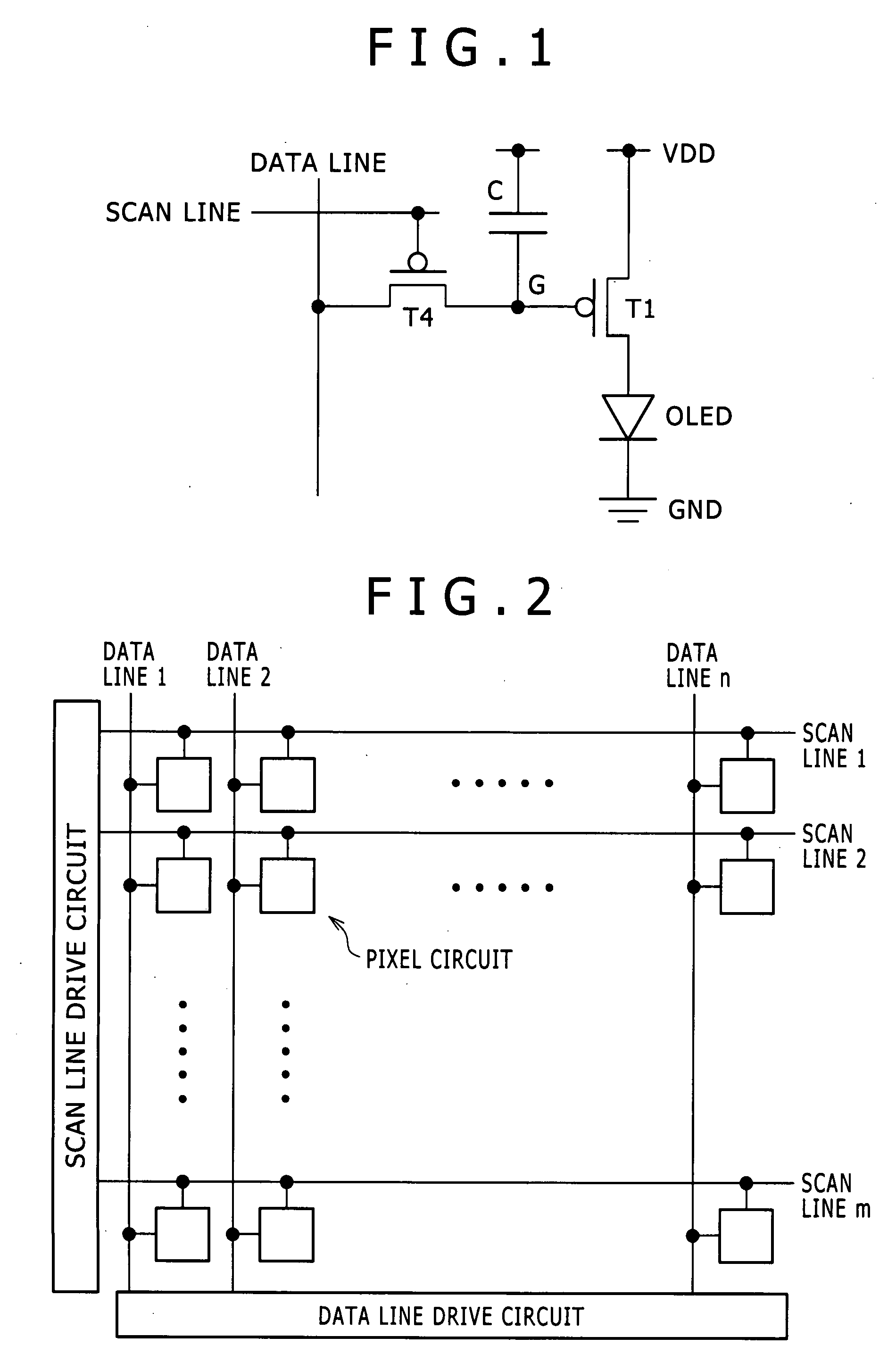
[0035]Preferred embodiments of the present invention will be described in detail below with reference to the accompanying drawings. FIG. 2 is a block diagram illustrating the overall configuration of an image display apparatus having a pixel circuit associated with an embodiment of the present invention which is integrated into an IC. As shown in the figure, the image display apparatus includes a pixel array unit in the center and a data line drive circuit and a scan line drive circuit which are provided around the pixel array unit. The pixel array unit includes scan lines 1 to m arranged in row directions, data lines 1 to n arranged in column directions, and pixel circuits each disposed where a scan line and a data line intersect each other. The scan line drive circuit is connected to the scan lines 1 to m and sequentially supplies a control signal for linear sequential scanning of the same circuits. The data line drive circuit is connected to the data lines 1 to n. and supplies a ...


PUM


Abstract

A pixel circuit is disposed where a scan line arranged in a row direction to supply a control signal and a data line arranged in a column direction to supply a video signal intersect each other. The pixel circuit includes: a sampling transistor; a drive transistor; a capacitor connected between the current path end of the sampling transistor and the gate of the drive transistor; and a light-emitting device connected to the current path end of the drive transistor. The pixel circuit connects the mobility with negative feedback during a mobility connection period.

Description

CROSS REFERENCES TO RELATED APPLICATIONS[0001]The present invention contains subject matter related to Japanese Patent Application JP 2006-226754 filed with the Japan Patent Office on Aug. 23, 2006, the entire contents of which being incorporated herein by reference.BACKGROUND OF THE INVENTION[0002]1. Field of the Invention[0003]The present invention relates to a pixel circuit for current-driving a light-emitting device in each pixel. The invention relates particularly to an active pixel circuit which controls the amount of current supplied to a light-emitting device such as organic EL device using insulated gate field effect transistors disposed in the pixel circuit. The invention relates more specifically to a technique of correcting variations in mobility of a drive transistor adapted to drive a light-emitting device formed in each pixel circuit.[0004]2. Description of the Related Art[0005]In an image display apparatus such as liquid crystal display, a number of liquid crystal pi...

Claims


Application Information

Patent Timeline
IPC IPC(8): G09G3/32H05B44/00
CPCG09G3/3233G09G3/3291G09G2300/0417G09G2300/0426G09G2330/021G09G2300/0852G09G2300/0861G09G2310/06G09G2300/0819G09G3/30G09G3/20G09G3/32
Inventor YUMOTO, AKIRAASANO, MITSURUJINTA, SEIICHIRO
Owner SONY CORP
Why Eureka
Try Eureka