Surge Absorber
a technology of absorber and absorber, which is applied in the direction of overvoltage protection resistor, emergency protective arrangement for limiting excess voltage/current, and arrangement responsive to excess voltage, etc., can solve the problem that the property of the coating film cannot be sufficiently achieved, the life span is required, and the effect of excellent adhesion and long life span
- Summary
- Abstract
- Description
- Claims
- Application Information
AI Technical Summary
Benefits of technology
Problems solved by technology
Method used
Image
Examples
experimental example 1
[0158] Next, a surge absorber according to the present invention will be described by Experimental Example in detail with reference to FIGS. 22 and 23.
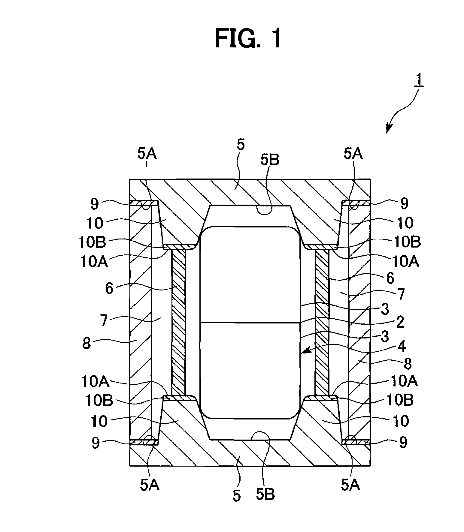
[0159] The surge absorber 50 according to the embodiment of FIG. 5 and a conventional surge absorber without the oxide film 33B and the cylindrical glass member 6 were mounted on boards, respectively, and the life spans thereof were compared.
[0160] More specifically, in Example 1, the result of repeatedly applying surge current shown in FIG. 22 to the surge absorber by a predetermined number of times and measuring a discharge start voltage (V) between gaps at this time is shown in FIG. 23.
[0161] In the conventional surge absorber, when the surge current is repeatedly applied, a large amount of metallic component of the metal electrode of the main discharge electrode member is scattered and the metallic component is deposited in a micro gap within a relatively short time. Accordingly, the discharge start voltage between the gaps is ...
experimental example 2
[0164] Next, a surge absorber according to the present invention will be described by Example 2 in detail with reference to FIGS. 22 and 24.
[0165] The surge absorber 70 according to the second modified example of the embodiment of FIG. 7 and the conventional surge absorber without the oxide film 33B and the granular glass members 106 were mounted on boards, respectively, and the life spans thereof were compared.
[0166] More specifically, in Example 2, the result of repeatedly applying surge current shown in FIG. 22 to the surge absorber by a predetermined number of times and measuring a discharge start voltage (V) between gaps at this time is shown in FIG. 24.
[0167] In the conventional surge absorber, when the surge current is repeatedly applied, a large amount of metallic component of the main discharge electrode member is scattered and the metallic component is deposited in a micro gap within a relatively short time. Accordingly, the discharge start voltage between the gaps is r...
experimental example 3
[0171] Next, a surge absorber according to the present invention will be described by Experimental Example in detail with reference to FIGS. 22 and 25.
[0172] The surge absorber 80 according to the third modified example of the fifth embodiment and the conventional surge absorber without the oxide film 33B and the glass coating film 25 were mounted on boards, respectively, and the life spans thereof were compared.
[0173] More specifically, in Experimental Example, surge current shown in FIG. 22 was repeatedly applied to the surge absorber by a predetermined number of times and the result of measuring a discharge start voltage (V) between gaps at this time is shown in FIG. 25.
[0174] In the conventional surge absorber, when the surge current is repeatedly applied, a large amount of metallic component of the main discharge electrode member is scattered and the metallic component is deposited in a micro gap within a relatively short time. Accordingly, the discharge start voltage betwee...
PUM
| Property | Measurement | Unit |
|---|---|---|
| width | aaaaa | aaaaa |
| width | aaaaa | aaaaa |
| aspect ratio | aaaaa | aaaaa |
Abstract
Description
Claims
Application Information
 - R&D
- Intellectual Property
- Life Sciences
- Materials
- Tech Scout
- Unparalleled Data Quality
- Higher Quality Content
- 60% Fewer Hallucinations
Browse by: Latest US Patents, China's latest patents, Technical Efficacy Thesaurus, Application Domain, Technology Topic, Popular Technical Reports.
© 2025 PatSnap. All rights reserved.Legal|Privacy policy|Modern Slavery Act Transparency Statement|Sitemap|About US| Contact US: help@patsnap.com


