
High Thermal Conductivity Mica Paper Tape

a mica paper and thermal conductivity technology, applied in the field of thermal conductivity mica paper tape, can solve the problems of reducing the efficiency and durability of the components as well as the equipment as a whole, and other problems of the prior art, and achieve the effects of high electrical resistivity and resistance, high thermal conductivity (htc) materials, and convenient us

Inactive Publication Date: 2008-02-28
SIEMENS ENERGY INC
View PDF98 Cites 51 Cited by
  • Summary
  • Abstract
  • Description
  • Claims
  • Application Information

AI Technical Summary

Benefits of technology

[0007] With the foregoing in mind, methods and apparatuses are consistent with the present invention, facilitates the thermal conductivity of insulating paper by mixing high thermal conductivity (HTC) materials onto and / or into the host matrix of the insulating paper. The HTC materials of the present invention can be of a variety of types, such as nanofillers or surface coatings, and both nanofillers and surface coatings each comprise various sub-groups unto themselves. The HTC materials can be added to the mica paper at a variety of stages, such as when the paper is in its raw materials, or substrate, stage, when the paper is being formed, or after the paper has been formed. Mica is a particular kind of substrate for insulating paper due to its high electrical resistivity and resistance to electrical discharges and electrical breakdown processes.
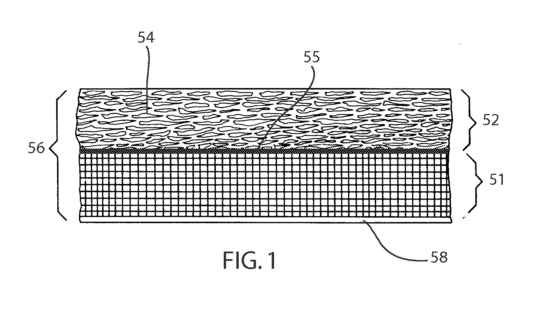
[0009] Although the thermal conductivity of the tape is increased when HTC materials are added to a fibrous backing as a back coating, so is the overall tape thickness. Since the tapes are generally used in multiple layers, tape thickness becomes a limiting factor in most applications, and applying more layers of a thinner tape can be better than applying fewer layers of a thicker tape. It has been found, however, that certain combinations of HTC materials in a backcoating can reduce the tape thickness in comparison with conventional backcoatings without interfering with the desired level of thermal conductivity. A thinner tape allows for more windings, thereby increasing the voltage endurance.

Problems solved by technology

Good electrical insulators, by their very nature, also tend to be good thermal insulators, which is undesirable.
Thermal insulating behavior, particularly for air-cooled electrical equipment and components, reduces the efficiency and durability of the components as well as the equipment as a whole.
Other problems with the prior art also exist, some of which will be apparent upon further reading.

Method used


Image

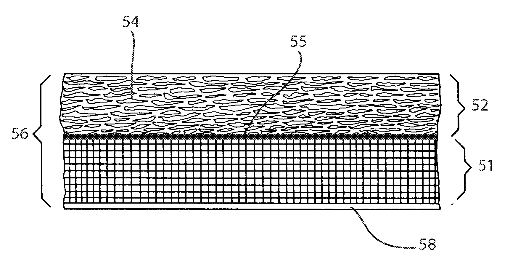
  • High Thermal Conductivity Mica Paper Tape
  • High Thermal Conductivity Mica Paper Tape

Examples


Embodiment Construction

[0024] The present invention provides for the incorporation of high thermal conductivity (HTC) materials into and onto the substrate used in paper insulation, such as the types used in electrical insulating tapes. Also the HTC materials may be added in addition or in substitution, to other components of the tape, such as the fibrous backing.

[0025] Insulating tapes tend to comprise a layer, such as mica, that is formed into a paper, that is often then impregnated with resin or accelerator or both. Before or after being impregnated, the paper used in tapes is added to a high tensile strength backing, such as glass or polymer film. The insulating tape acts as a very good electrical insulator, but also insulates thermally as well, which is an undesired side effect.

[0026] It is therefore desired to increase the thermal conductivity of the substrate and the matrix. As used herein substrate refers to the backing layer of the tape, which may be glass fabric or a porous polymer film, while...


PUM

PropertyMeasurementUnit
Fractionaaaaaaaaaa
Fractionaaaaaaaaaa
Fractionaaaaaaaaaa

Abstract

The impregnation of a composite tape (56) having a porous matrix with HTC particles provides for permeating a fabric substrate layer (51) of the composite tape with HTC particles and impregnating an impregnating resin into the composite tape (51). The HTC particles in the fabric (51) layer are comprised of a meso-micro mixture, which is between 1:4 to 4:1 meso sized particles to micro sized particles. Other smaller particles may also be included at lesser concentrations. The impregnating resin itself may also contain HTC particles.

Description

CROSS-REFERENCE TO RELATED APPLICATIONS [0001] This application is a continuation-in-part of U.S. application Ser. No. 11 / 396,990 “Composite Insulation Tape with Loaded HTC Materials” filed Apr. 3, 2006, by Smith, et al., which is in turn a continuation-in-part of U.S. application Ser. No. 11 / 106,846 “Insulation Paper with High Thermal Conductivity Materials” filed Apr. 15, 2005, by Smith, et al., which in turn claims priority to U.S. provisional application 60 / 580,023, filed Jun. 15th, 2004, by Smith, et al., all of which are incorporated herein by reference.FIELD OF THE INVENTION [0002] The field of the invention relates to insulation tapes, and more particularly to the loading of HTC materials into composite tapes. BACKGROUND OF THE INVENTION [0003] With the use of any form of electrical appliance, there is a need to electrically insulate conductors. With the push to continuously reduce the size and to streamline all electrical and electronic systems there is a corresponding need...

Claims


Application Information

Patent Timeline
IPC IPC(8): B32B5/16C09J5/02
CPCB32B5/16Y10T428/254B32B5/30B32B27/20B32B29/02B32B2255/04B32B2255/24B32B2260/021B32B2260/025B32B2260/046B32B2264/102B32B2264/104B32B2264/108B32B2307/206B32B2307/302B32B2405/00B32B2457/00B32B2581/00B32B2605/00H01B3/004H01B3/04H01B19/02B32B5/24Y10T428/25
Inventor STEVENS, GARY C.SMITH, JAMES D.B.WOOD, JOHN W.LUTZ, ANDREAS
Owner SIEMENS ENERGY INC
Learn More