Light emitting packages and methods of making same

a technology of light emitting packages and light-emitting components, applied in the field of light-emitting components, can solve the problems of insufficient light-emitting components, inability to meet the requirements of light-emitting components,

Active Publication Date: 2008-03-06
GE LIGHTING SOLUTIONS LLC
View PDF60 Cites 221 Cited by
  • Summary
  • Abstract
  • Description
  • Claims
  • Application Information

AI Technical Summary

Problems solved by technology

Additionally, the chip typically emits incoherent and unfocused radiation.
Existing light emitting packages have been less than fully satisfactory.
Soft molded encapsulants, for example, are typically prone to damage due to abrasion, exposure to corrosive chemicals, or so forth.
Moreover, for illumination it is typically not desired to focus the light.
Multiple chip packages provide greater illumination, but generally increase package complexity.
Baretz discloses a phosphor contained in an encapsulant disposed inside the housing, The complexity of multiple chip packages such as those of Lowery and Baretz can adversely impact manufacturability, reliability, and manufacturing costs.

Method used


Image

  • Light emitting packages and methods of making same
  • Light emitting packages and methods of making same
  • Light emitting packages and methods of making same

Examples


Embodiment Construction

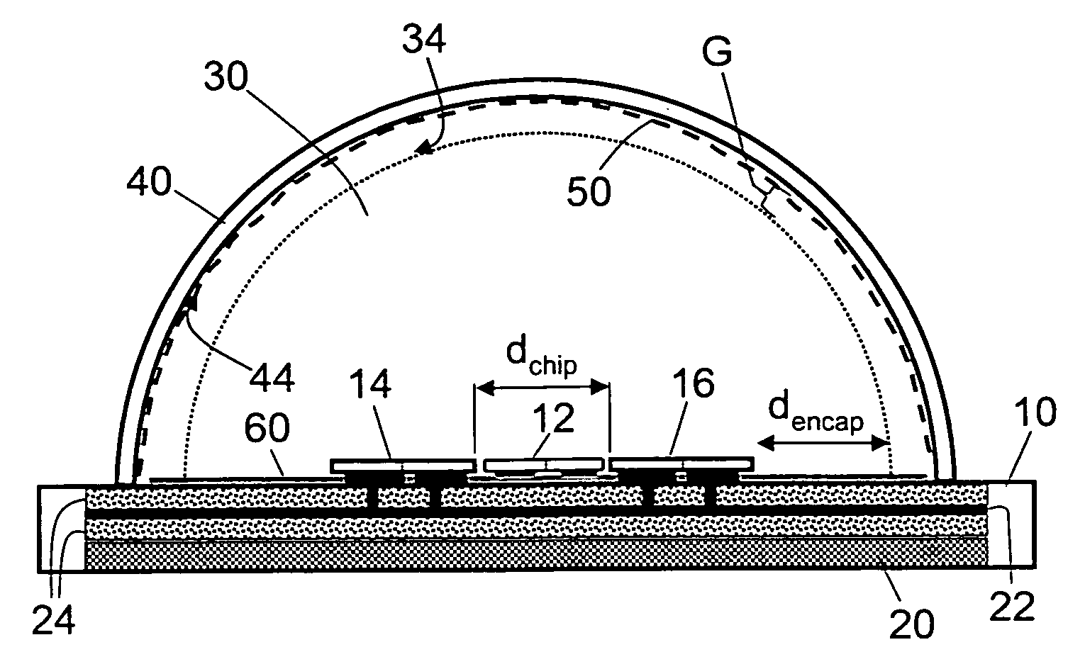
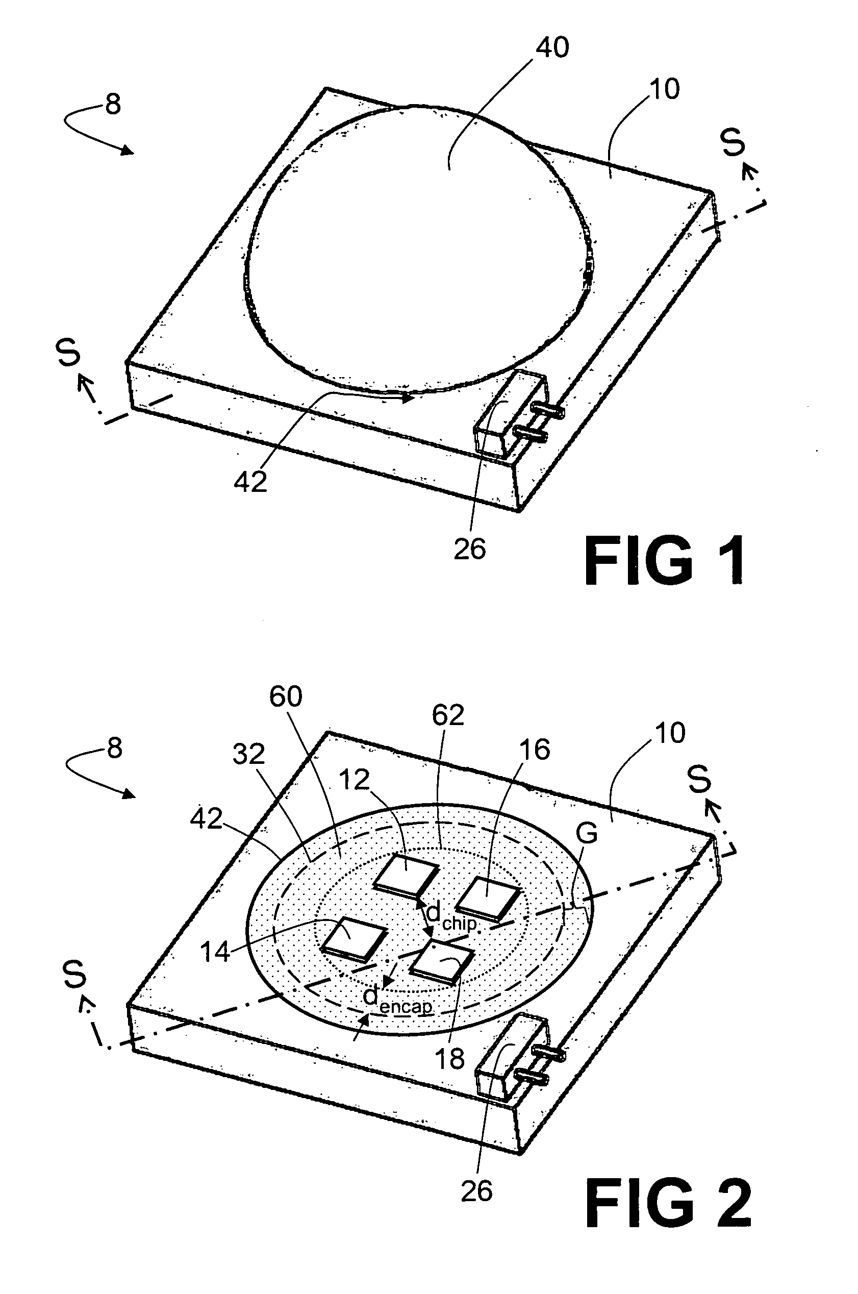
[0016]With reference to FIGS. 1-3, a light emitting package 8 includes a board 10, such as a printed circuit board, metal-core printed circuit board, insulated heat-sinking board, or so forth on which a plurality of light emitting dice or chips 12, 14, 16, 18 are disposed. The board 10 is preferably substantially thermally conductive. For example, a metal core printed circuit board can be employed. In the illustrated embodiment, four light emitting dice or chips 12, 14, 16, 18 are disposed on the board 10; however, the number of dice or chips can be one, two, three, four, five, or more. The chips 12, 14, 16, 18 can be group III-nitride blue, violet, or ultraviolet light emitting diode chips, red group III-phosphide or group III-arsenide light emitting diode chips, II-VI light emitting diode chips, IV-VI light emitting diode chips, silicon or silicon-germanium light emitting diode chips, or the like. Although semiconductor light emitting diode chips 12, 14, 16, 18 are illustrated her...


PUM


Abstract

In a light emitting package (8), at least one light emitting chip (12, 14, 16, 18) is supported by a board (10). A light transmissive encapsulant (30) is disposed over the at least one light emitting chip and over a footprint area (32) of the board. A light transmissive generally conformal shell (40) is disposed over the encapsulant and has an inner surface (44) spaced apart by an air gap (G) from, and generally conformal with, an outer surface (34) of the encapsulant. At least one phosphor (50) is disposed on or embedded in the conformal shell to output converted light responsive to irradiation by the at least one light emitting chip. A thermally conductive filler material disposed in the generally conformal shell (40) is effective to enhance a thermal conductivity of the composite shell material to a value higher than 0.3 W / (m.K).

Description

BACKGROUND[0001]The following relates to the lighting arts, and to light emitting packages based on one or more light emitting chips and to methods for making same.[0002]Light emitting packages based on light emitting chips, such as semiconductor light emitting diode chips, organic light emitting diode chips, semiconductor laser chips, and so forth, are increasingly used for illumination. Each chip typically produces radiation that is saturated light at a single color point, such as red light, green light, blue light, or so forth, or violet or ultraviolet light over a narrow spectral range. It is known to operatively couple the chip with a wavelength converting phosphor so as to produce a desired light output such as an approximate white light output. Additionally, the chip typically emits incoherent and unfocused radiation. (An exception are laser diode chips, which may produce coherent and directional radiation.) It is further known to couple the LED (optionally coated with phosph...

Claims


Application Information

Patent Timeline
Patent Type & Authority Applications(United States)
IPC IPC(8): H01L33/00H01L21/00H01L33/50H01L33/54H01L33/58H01L33/64
CPCG02F1/353H01L25/0753H01L33/507H01L33/54H01L33/58H01L33/644H01L2924/0002H01S5/02288H01S5/02296H01L2924/00H01S5/02257H01S5/02253H01S5/0087
Inventor REGINELLI, JAMESAANEGOLA, SRINATH K.RADKOV, EMIL
Owner GE LIGHTING SOLUTIONS LLC
Why Eureka
Try Eureka