
Organic light emitting display and driving method thereof

a technology of light-emitting display and driving method, which is applied in the direction of instruments, discharge tube luminescnet screens, static indicating devices, etc., can solve the problems of difficult to accurately express the brightness difference between adjacent gradations, difficulty in realizing the exact expression of desired gradations, and different threshold voltages and electron mobilities of transistors in pixel circuits to achieve the effect of reducing manufacturing costs

Inactive Publication Date: 2008-03-06
SAMSUNG DISPLAY CO LTD
View PDF8 Cites 27 Cited by
  • Summary
  • Abstract
  • Description
  • Claims
  • Application Information

AI Technical Summary

Benefits of technology

The present invention provides an organic light emitting display and a method for driving it that overcomes the limitations and disadvantages of related art. The invention uses a frame divided into a plurality of sub-frames to display an image with uniform luminance and reduces manufacturing cost. The method includes sequentially providing a scan signal to scan lines, supplying an output signal to an output line when the scan signal is supplied, separating the output signal into a plurality of data signals, and simultaneously providing the plurality of data signals to a corresponding plurality of data lines. The invention also includes a demultiplexer controller and a storage section with a data capacitor between each data line and the demultiplexer. The plurality of data signals may include a red data signal, a blue data signal, and a green data signal. The simultaneous providing of the plurality of data signals may occur during a second time period of a supply period of the scan signal. The invention provides an improved display with reduced manufacturing cost and improved image quality.

Problems solved by technology

However, exact expression of desired gradations may not be realized.
In practice, it may be difficult to accurately express a brightness difference between adjacent gradations using analog driving noted above.
Further, transistors in the pixel circuits may have differing threshold voltages and electron mobilities due to a process deviation.
Thus, the pixels may generate light of different gradations with respect to the same gradation voltage, resulting in non-uniform luminance.

Method used


Image

  • Organic light emitting display and driving method thereof
  • Organic light emitting display and driving method thereof
  • Organic light emitting display and driving method thereof

Examples


first embodiment

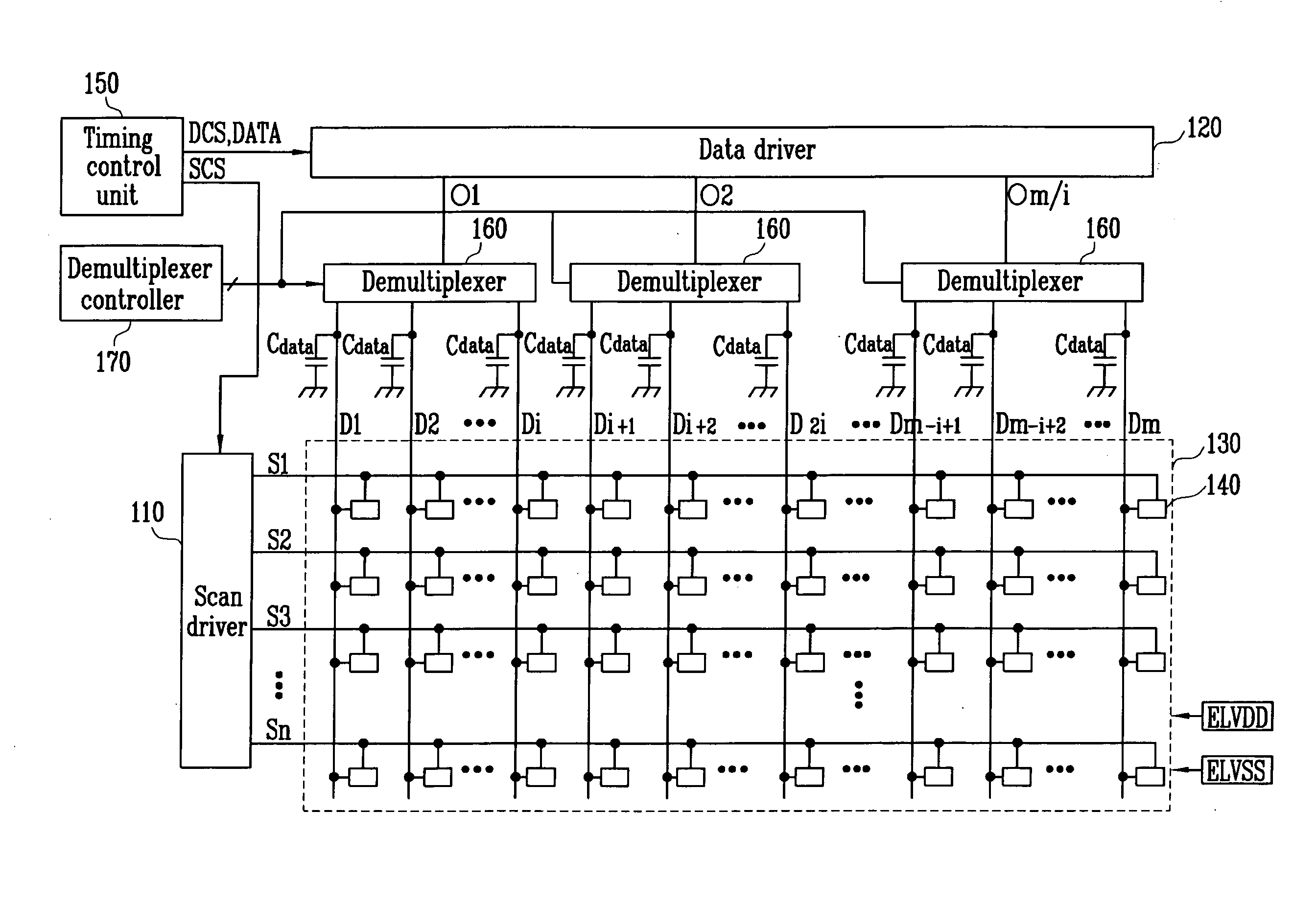
[0031]FIG. 1 illustrates an organic light emitting display according to the present invention

[0032]With reference to FIG. 1, the organic light emitting display according to an embodiment of the present invention may include a scan driver 110, a data driver 120, a pixel portion 130, a timing control unit 150, demultiplexers 160, a demultiplexer controller 170, and data capacitors Cdata.

[0033]The timing control unit 150 may generate a data driving signal DCS and a scan driving signal SCS corresponding to external synchronizing signals. The data driving signal DCS generated from the timing control unit 150 may be provided to the data driver 120, and the scan driving signal SCS may be provided to the scan driver 110. Further, the timing control unit 150 may provide externally supplied data DATA to the data driver 120.

[0034]The data driver 120 may sequentially provide a plurality of data signals to respective output lines O1 to Om / i, where i is a natural number greater than two, every ho...

second embodiment

[0054]An organic light emitting display according to the present invention as shown in FIG. 6 may solve the aforementioned problems.

[0055]FIG. 6 illustrates an organic light emitting display according to a second embodiment of the present invention. Elements of FIG. 6 corresponding to those of FIG. 1 are designated by the same symbols, and the description thereof is omitted.

[0056]Referring to FIG. 6, the organic light emitting display according to a second embodiment of the present invention further includes delay sections 162 coupled between demultiplexers 160 and data lines D1 to Dm. The demultiplexers 160 divides a signal from the output line O into a plurality of i data signals, and supplies the plurality of I data signals to a corresponding plurality of data lines D. Data signals supplied from the demultiplexer 160 may be temporarily stored in the data capacitors Cdata.

[0057]When a clock signal CLK from the demultiplexer controller 170 is supplied to the delay sections 162, the...


PUM


Abstract

An organic light emitting display adapted to be driven using a frame divided into a plurality of sub-frames includes a scan driver adapted to sequentially provide a scan signal to scan lines every sub-frame, a data driver adapted to provide an output signal to an output line when the scan signal is supplied to the data driver, a demultiplexer adapted to separate the output signal into a plurality of data signals, and a storage section adapted to simultaneously provide the plurality of data signals from the demultiplexer to a corresponding plurality of data lines.

Description

BACKGROUND OF THE INVENTION[0001]1. Field of the Invention[0002]Embodiments of the present invention relate to an organic light emitting display and a driving method thereof. More particularly, embodiments of the present invention relate to an organic light emitting display and a method for driving the same, which is applicable to a digital drive.[0003]2. Description of the Related Art[0004]Recently, various flat panel displays having reduced weight and volume compared with cathode ray tubes (CRT) have been developed. Flat panel displays include liquid crystal displays (LCDs), field emission displays (FEDs), plasma display panels (PDPs), and organic light emitting displays.[0005]Organic light emitting displays make use of organic light emitting diodes (OLEDs) that emit light by re-combining electrons and holes. The organic light emitting display may provide high response speed and small power consumption.[0006]The OLED generates light of a predetermined luminance corresponding to a ...

Claims


Application Information

Patent Timeline
Patent Type & Authority Applications(United States)
IPC IPC(8): G09G3/30
CPCG09G3/2003G09G3/2022G09G2310/0297G09G3/3291G09G3/3225
Inventor RYU, DO HYUNGKIM, DO IK
Owner SAMSUNG DISPLAY CO LTD
Learn More