
Camera shake correction mechanism and image capture apparatus

Inactive Publication Date: 2008-03-06
SONY CORP
View PDF6 Cites 31 Cited by
  • Summary
  • Abstract
  • Description
  • Claims
  • Application Information

AI Technical Summary

Benefits of technology

[0011]Accordingly, it is desirable to provide a camera-shake correction mechanism, as well as an image-capture apparatus equipped therewith, which is capable of reducing thermal noise by increasing heat dissipation from the imaging device even in the sensor shift camera-shake correction method. The present invention is made in view of such circumstances.
[0022]According to a camera-shake correction mechanism of the present invention and an image-capture apparatus equipped therewith, thermal noise can be reduced since heat dissipation of the imaging device is improved.

Problems solved by technology

Image-capture apparatuses that have a camera-shake correction function are likely to give rise to thermal noise since the imaging device therein tends to generate heat.
The third correction method is advantageous in that it does not require a lens for correction and in that compact high picture quality shaking correction can be realized, but since it is one in which the imaging device moves, it is difficult to efficiently dissipate heat from and cool the imaging device.
The heat dissipating method in Patent Document 1 calls for a cooling plate between the imaging device and the substrate, and therefore, does not allow for efficient heat dissipation from the imaging device.

Method used


Image

  • Camera shake correction mechanism and image capture apparatus
  • Camera shake correction mechanism and image capture apparatus
  • Camera shake correction mechanism and image capture apparatus

Examples


Embodiment Construction

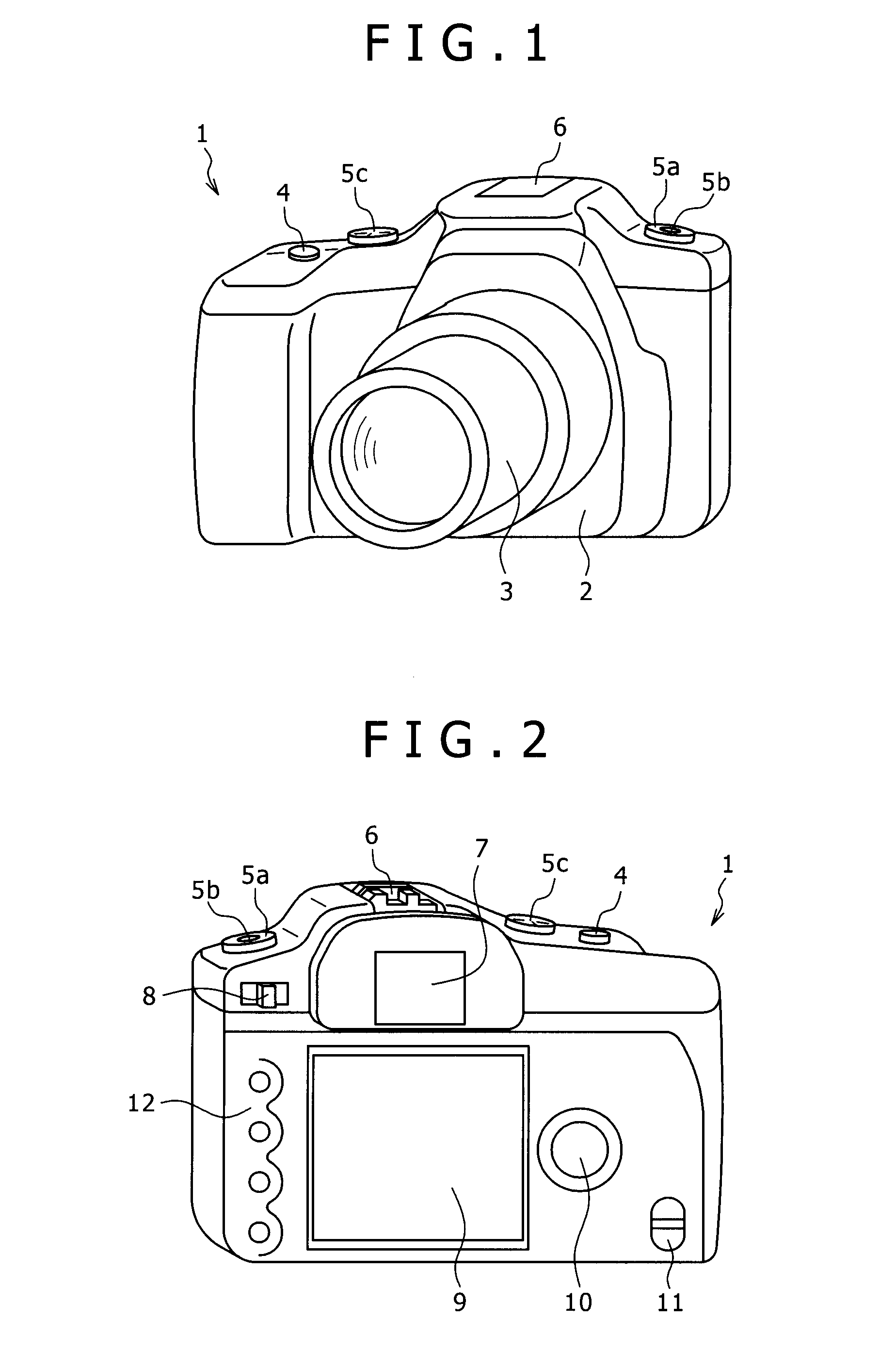
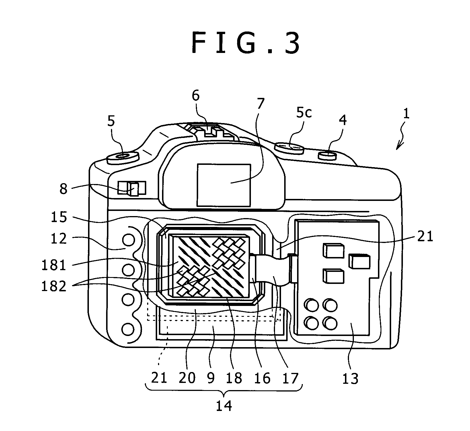
[0039]FIG. 1 is a perspective view of a digital still camera, which is an image-capture apparatus related to an embodiment of the present invention, as seen from the front side. FIG. 2 is a perspective view of the digital still camera as seen from the rear side. FIG. 3 is a perspective view that indicates the interior of the digital still camera as seen from the rear side.

[0040]A digital still camera 1 shown in FIG. 1 is an embodiment of a single-lens reflex digital still camera. A lens tube 3 is detachably provided on the front side of a camera body 2 in an approximately central portion. A grip section, which is to be held by the user's hand, is formed on the front left end section of the camera body 2. A shutter button 4 is provided on the upper end section of this grip section. A function dial 5a and a function button 5b are provided on the front upper right end section of the camera body 2, and a mode dial 5c is provided on an approximately front upper left end section of the ca...


PUM


Abstract

There is provided a camera-shake correction mechanism by which camera shaking is corrected for by moving an imaging device on a plane that is orthogonal to an optical axis and in directions that are mutually orthogonal. The mechanism includes a heat dissipating mechanism that diffuses heat from the imaging device into atmosphere from a rear surface of the imaging device.

Description

BACKGROUND OF THE INVENTION[0001]1. Field of the Invention[0002]The present invention relates to a camera-shake correction mechanism that is adopted as a shaking correction function and the like for a digital still camera, digital video camera and the like, and which corrects for camera shaking, as well as to an image-capture apparatus equipped with such a mechanism.[0003]2. Description of Related Art[0004]There are three types of mechanisms that correct for or absorb the misalignment of the optical axis such as a camera-shake correction mechanism, anti-vibration mechanism and the like for an image-capture apparatus.[0005]First, there is the “electronic camera-shake correction method” in which a blurred image received by an imaging device is corrected to a clearer image by having the position and color of the blurred image corrected electronically by some program.[0006]Second, there is the “optical camera-shake correction method” in which a correction lens whose photographic lens is...

Claims


Application Information

Patent Timeline
IPC IPC(8): H04N5/228
CPCH04N5/2253H04N5/23287H04N5/23248H04N23/54H04N23/68H04N23/687
Inventor ORIHASHI, MASAKISUZUKI, KAZUHIKOYASUHARA, RYUICHIKAMAYA, NAOKI
Owner SONY CORP
Learn More