
Electromagnetic Interference Shielding Structure Including Carbon Nanotubes and Nanofibers

a technology of electromagnetic interference and shielding structure, which is applied in the field of materials useful for shielding electromagnetic radiation, can solve the problems of increasing fabrication cost, increasing device weight, and corrosion problems in long-term applications

Inactive Publication Date: 2008-03-06
FLORIDA STATE UNIV RES FOUND INC
View PDF12 Cites 86 Cited by
  • Summary
  • Abstract
  • Description
  • Claims
  • Application Information

AI Technical Summary

Benefits of technology

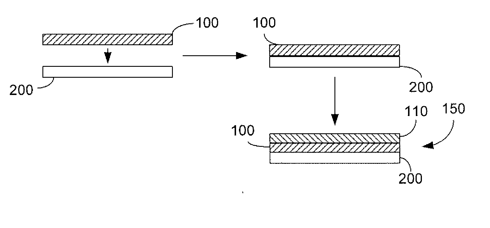
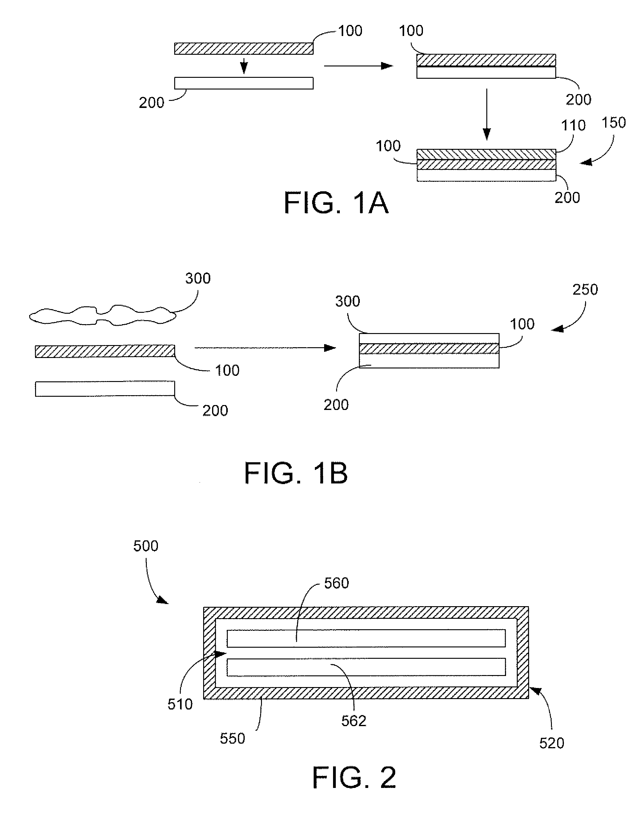
[0011] In yet another aspect, a composite structure for shielding electromagnetic interference is provided. In one embodiment, the composite structure includes at least one nanoscale fiber film which comprises a plurality of nanoscale fibers; and one or more structural materials combined with the at least one nanoscale fiber film to provide a composite material structure for shielding electromagnetic interference. In one embodiment, the composite structure includes a laminate structure. The composite material structure may include two or more layers of the nanoscale fiber film. In one embodiment, the one or more structural materials includes an epoxy or another polymeric material. The one or more structural materials may be electrically non-conductive, may include a solid foam or porous substrate, and may comprise a glass fiber material. In a particular embodiment, the one or more structural materials are impregnated into spaces among the plurality of nanoscale fibers. The composite structure may have an average electromagnetic wave attenuation of at least about 21 dB between the frequencies of about 200 MHz and about 500 MHz, and at least about 30 dB between the frequencies of about 4 GHz and about 18 GHz.

Problems solved by technology

Unfortunately, these methods add significant weight to the devices, increase fabrication costs, and may present corrosion problems in long term applications.

Method used


Image

  • Electromagnetic Interference Shielding Structure Including Carbon Nanotubes and Nanofibers
  • Electromagnetic Interference Shielding Structure Including Carbon Nanotubes and Nanofibers
  • Electromagnetic Interference Shielding Structure Including Carbon Nanotubes and Nanofibers

Examples


example 1

EMI Attenuation of a Foam Sandwich Composite Structure with Two Layers of Randomly Dispersed SWNT Films

[0045] An EMI shielding structure which included randomly dispersed nanotube films was tested for radio frequency (RF) attenuation.

[0046] Purified SWNTs were obtained from Carbon Nanotechnologies Inc. (Houston, Tex.). Nanotube films were prepared from the SWNTs as follows: The SWNTs were dispersed with sonification into distilled water containing Triton X-100 surfactant in order to form a stable suspension. The SWNT concentration in the suspension was 40 mg / L. Next, about 12 to 15 liters of suspension was filtered using a custom-made filter with a 0.45 μm nylon filter membrane from Millipore, Inc. (Billerica, Mass.). The filtration process yielded a SWNT film (i.e., a sheet or membrane). The film was then washed using isopropanol. The length and width dimensions of the SWNT film were about 9 inches by 9 inches.

[0047] Composite structures were prepared as follows: The film was cu...

example 2

EMI Attenuation of a Foam Sandwich Composite Structure with Two Layers of Aligned SWNT Films

[0050] An EMI shielding composite structure which included magnetically aligned nanotube films was tested for RF attenuation. The composite structure was prepared and tested as described in Example 1, except that the SWNT films were produced under the influence of a magnetic field to align the nanotubes. The SWNT films were cut and assembled with foam such that the two layers of SWNT films had the same alignment direction along the 4-inch direction of the samples.

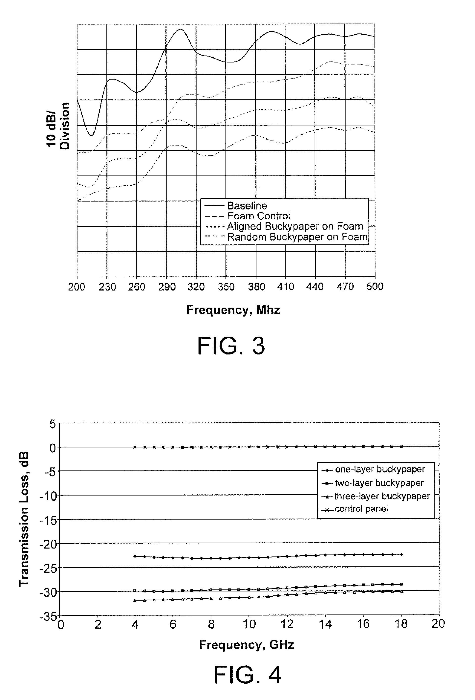
[0051]FIG. 3 shows the results of the EMI shielding tests over a low frequency range between 200 MHz and 500 MHz for the aligned composite structure in comparison to a baseline (empty or without any shielding materials) and a 2 mm thick ROHACELL PMI foam panel (control panel). The tests showed that as compared to the pure foam control sample, the composite structure achieved attenuation as great as 16 dlB at about 500 MHz, and an a...

example 3

EMI Shielding Composite

Foam with One, Two, and Three Layers of Randomly Dispersed SWNT Film Surface Skins

[0052] EMI shielding composite structures which included one, two, and three layers of randomly dispersed nanotube films were tested for RF attenuation. The composite structure was prepared and tested as described in Example 1, except that the EMI shielding test was performed over a 4 GHz and 180 Hz range.

[0053]FIG. 4 shows the results of the EMI shielding tests in comparison to a foam panel (control panel). The tests showed that as compared to the pure foam control sample, the composite structure achieved attenuation as great as 30 dB.


PUM

PropertyMeasurementUnit
thicknessaaaaaaaaaa
thicknessaaaaaaaaaa
frequenciesaaaaaaaaaa

Abstract

Electromagnetic interference (EMI) shielding structure and methods of making such structures are provided. In one case, a method is provided for making a lightweight composite structure for electromagnetic interference shielding, including the steps of providing a nanoscale fiber film which comprises a plurality of nanoscale fibers; and combining the nanoscale fiber film with one or more structural materials to form a composite material which is effective as an electromagnetic interference shielding structure. In another case, a method is provided for shielding a device which includes an electrical circuit from electromagnetic interference comprising the steps of providing a nanoscale fiber film which comprises a plurality of nanoscale fibers; and incorporating the nanoscale fiber film into an exterior portion of the device to shield an interior portion of the device from electromagnetic interference.

Description

CROSS-REFERENCE TO RELATED APPLICATIONS [0001] This application claims benefit of U.S. Provisional Application No. 60 / 747,879, filed May 22, 2006. This application is incorporated herein by reference.STATEMENT REGARDING FEDERALLY SPONSORED RESEARCH OR DEVELOPMENT [0002] This invention was made with U.S. government support under Award No. FA9550-05-1-0271 awarded by the Air Force Office of Scientific Research. The U.S. government has certain rights in the invention.BACKGROUND OF THE INVENTION [0003] This invention is generally in the field of materials useful for shielding electromagnetic radiation, and more particularly in the field of electromagnetic interference shielding structures that comprise films which include nanotubes, other nanofibers, and the like. [0004] Electromagnetic interference shielding structures are used to prevent electromagnetic radiation from interfering with the operation of electronic devices including but not limited to computer systems, communications equ...

Claims


Application Information

Patent Timeline
Patent Type & Authority Applications(United States)
IPC IPC(8): B05D5/12B29C65/00B29C65/02B29C65/48B32B33/00B32B5/12
CPCB32B5/02B32B33/00Y10T428/265Y10T156/10Y10T428/24132H05K9/009Y10T428/249953Y10T428/31504Y10T428/8305
Inventor LIANG, ZHIYONGWANG, BENZHANG, CHUN
Owner FLORIDA STATE UNIV RES FOUND INC
Learn More