
Means and method for marking tissue in a human subject

Inactive Publication Date: 2008-03-06
FISCHELL ROBERT E +1
View PDF7 Cites 25 Cited by
  • Summary
  • Abstract
  • Description
  • Claims
  • Application Information

AI Technical Summary

Benefits of technology

[0011]Locating the magnet within the breast is accomplished by means of a magnetometer probe that can take several different forms. One form is a total field magnetometer located near the distal end of the probe. Another embodiment of the magnet locating system is to use a vector magnetometer or a vector magnetic gradient detector. Such a gradient detector has the advantage of being able to automatically cancel out the earth's magnetic field and any local field whose gradient is (as would be expected) much smaller than the gradient of the magnetic field from the implanted magnet.

Problems solved by technology

In addition, the implantation of a small metal “clip” marker following large core biopsy under image guidance may be used when the visualized target has been substantially removed during the diagnostic procedure (thus compromising future successful localization).
The explosive growth of diagnostic imaging has increased the frequency of detection of small lesions throughout the body that cannot be seen or felt by the surgeon who is charged with the task of removing the suspected tissue volume.
These devices all have the significant limitation of requiring the image guided localization procedure immediately before the surgery.
The need for immediate preoperative localization creates logistical problems for radiology departments and operating room personnel.
Thus, a device that could be implanted by a radiologist at one time and then independently removed by a surgeon at another time on the day of the needed surgical procedure with no further patient preparation is desirable.
Although some have attempted solutions to these problems, a simple and cost effective approach has not yet been found.
These proposed devices all have one significant drawback in common: they are large and may be expected to be uncomfortable for patients.
This problem may be further compounded when these devices must remain in position for some length of time.
Although this system is workable, the metal detector for such small wires can only detect them within a comparatively close range of the suspected tissue volume.
Such tiny magnets have an extremely small field at any reasonable distance outside of a human breast because the close proximity of the north and south poles result in cancellation of the magnet's external field.

Method used


Image

  • Means and method for marking tissue in a human subject
  • Means and method for marking tissue in a human subject
  • Means and method for marking tissue in a human subject

Examples


Embodiment Construction

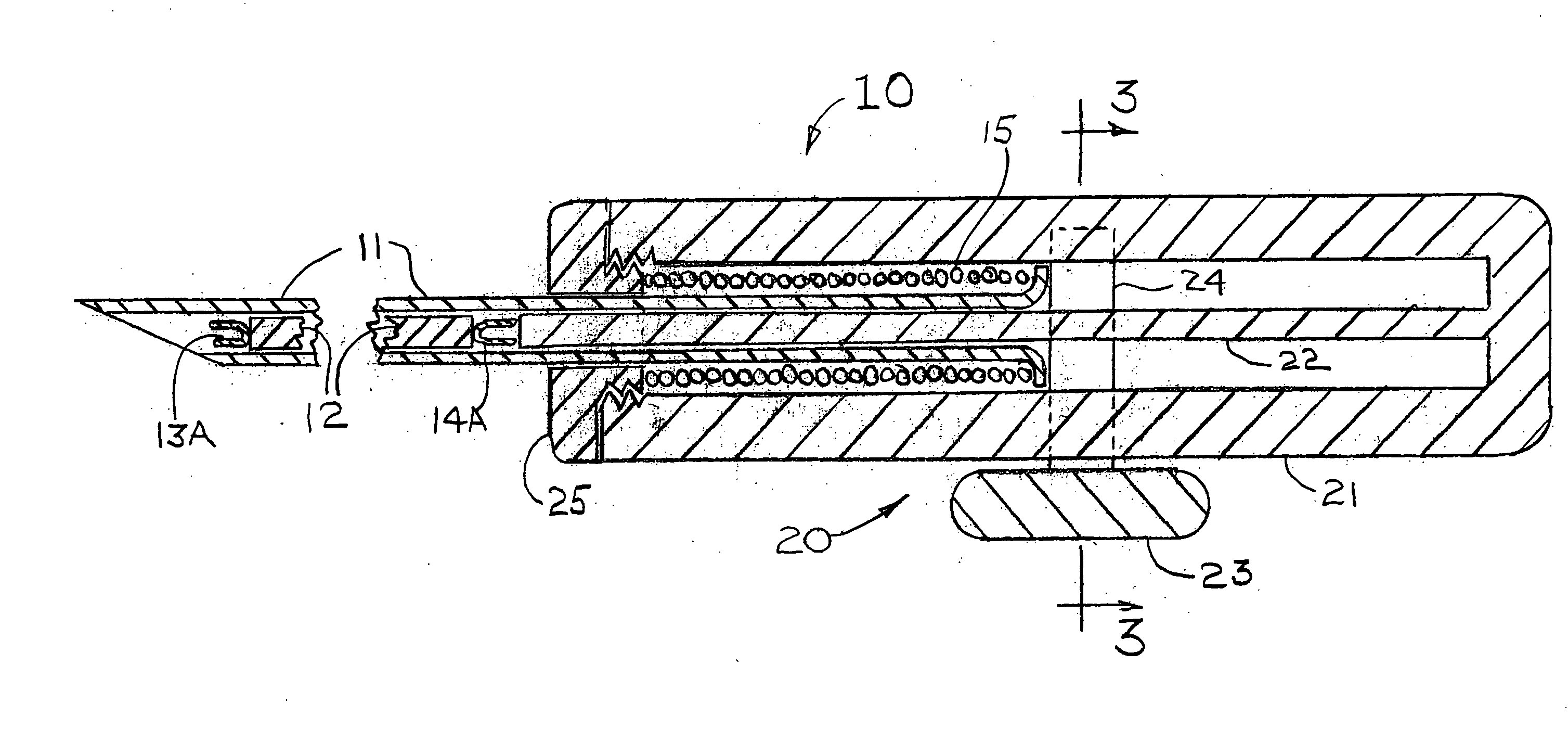
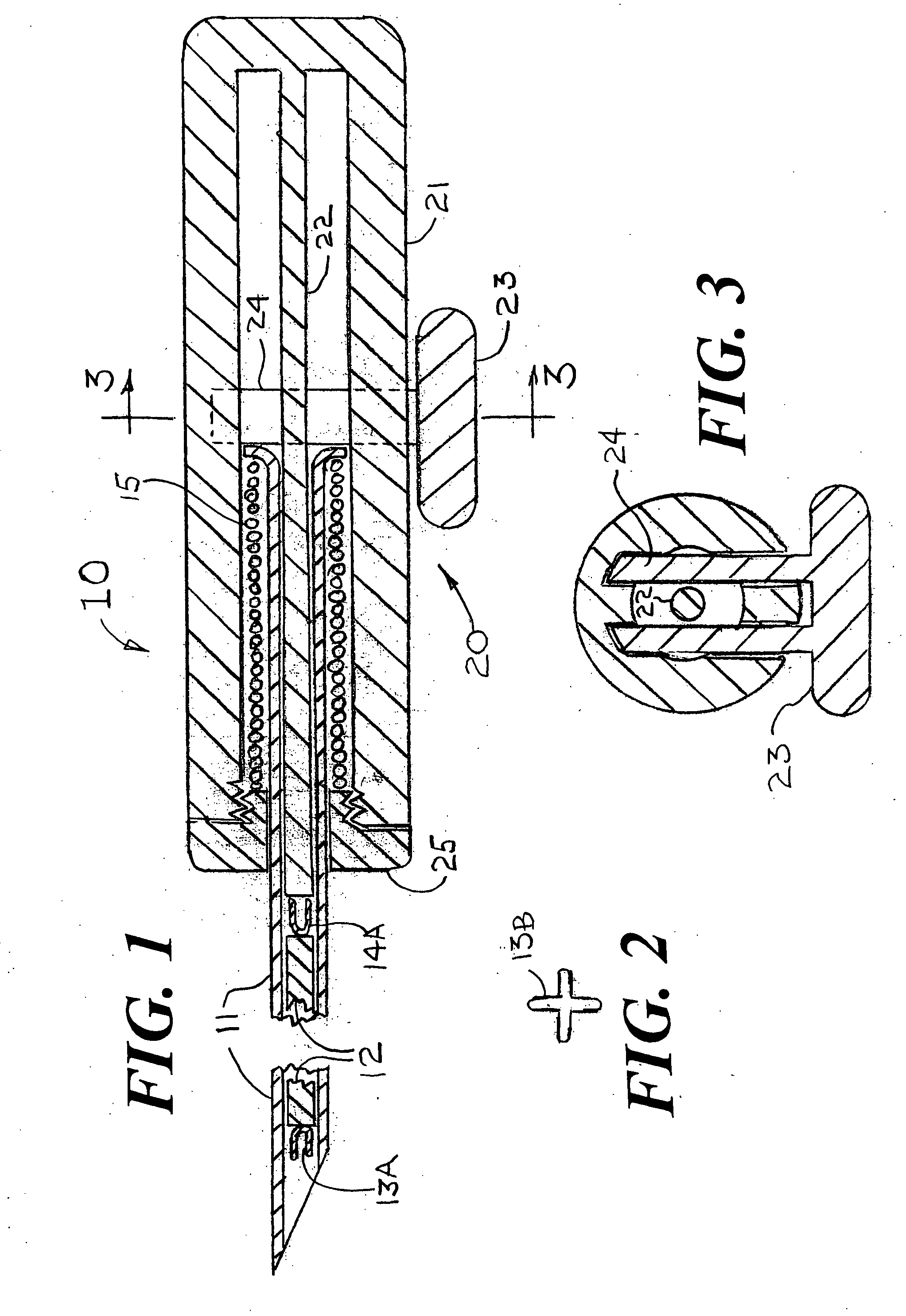
[0030]FIG. 1 shows a magnet injector 10 having a cannula 11 into which is placed a permanent magnet 12 having a pre-deployed distal anchor 13A fixedly attached at the magnet's distal end and a pre-deployed proximal anchor 14A fixedly attached at the magnet's proximal end. It is also conceived that the magnet could have one or more anchors deployed near the center of the magnet that also would be used to stabilize the position of the magnet within the breast. The shape of the deployed distal anchor 13B is shown in FIG. 2. The cannula 11 is positioned within a handle 20 that has an outer cylinder 21, an inner cylinder 22 and a spring release handle 23 that is attached to a spring holder 24 that keeps the spring 15 from expanding until the magnet 12 is ready for release within the suspected tissue volume. The distal end of the spring 15 is held by the end cap 25 and the proximal end of the spring is held by an expanded end section of the cannula 11. When the magnet 12 is placed into a ...


PUM


Abstract

Disclosed is a system for placing an elongated permanent magnet into a volume of tissue within a human body that is suspected of being cancerous. The magnet's position is then detected by a magnet locating system that is used by a surgeon to find and remove the suspected tissue volume including a margin of tissue to assure that any and all cancer cells have been excised. The magnet locating system includes a wireless probe that sends a signal to a range indication device that indicates the range from the end of the probe to the magnet implanted in the human body. This indication of distance to the magnet is preferably accomplished by an audio signal or a visual display.

Description

FIELD OF USE[0001]This invention is in the field of methods and devices for marking human tissue that may be cancerous so that tissue can be excised by a surgeon.BACKGROUND OF THE INVENTION[0002]The need for accurate preoperative image guided localization of nonpalpable breast lesions has been well described, and the frequency of use for this technique is increasing. Not only mammographically detected lesions require localization, but also lesions that may be found by any other imaging technique such as ultrasound, MRI, nuclear medicine or other technologies not yet described. Such localizations generally require the positioning of a temporary marker, most frequently constructed of a metal anchor on the end of a wire inserted through a needle that has been accurately positioned by image guidance prior to the release of the marker. See, Frank H. A., Hall F. M., Steer M. L., Preoperative Localization of Nonpalpable Breast Lesions Demonstrated by Mammography; New England Journal of Med...

Claims


Application Information

Patent Timeline
IPC IPC(8): A61B5/05
CPCA61B5/06A61B19/54A61B2019/5487A61B2019/5454A61B2019/5408A61B90/39A61B2090/3908A61B2090/3954A61B2090/3987
Inventor FISCHELL, ROBERT E.MULLEN, DAVID J.
Owner FISCHELL ROBERT E
Learn More