Method and apparatus for preheating ventilation air for a building

a technology for ventilation air and buildings, applied in lighting and heating apparatus, heating types, sustainable buildings, etc., can solve problems such as pressure drop in air flow, and achieve the effects of improving ventilation efficiency, simple and easy installation, and improving use efficiency

Inactive Publication Date: 2008-03-13
MATRIX ENERGY
View PDF15 Cites 11 Cited by
  • Summary
  • Abstract
  • Description
  • Claims
  • Application Information

AI Technical Summary

Benefits of technology

[0008]It is the purpose of the present invention to provide a solar air heating system that is simpler in construction, simpler and easier to install, more efficient in use, easier to service, and lends itself to a greater variety in design of the panel.

Problems solved by technology

While satisfactory, the use of a bottom horizontal collector duct can lead to a pressure drop in the air flow due to the abrupt change of direction of the air flow.

Method used


Image

  • Method and apparatus for preheating ventilation air for a building
  • Method and apparatus for preheating ventilation air for a building
  • Method and apparatus for preheating ventilation air for a building

Examples


Embodiment Construction

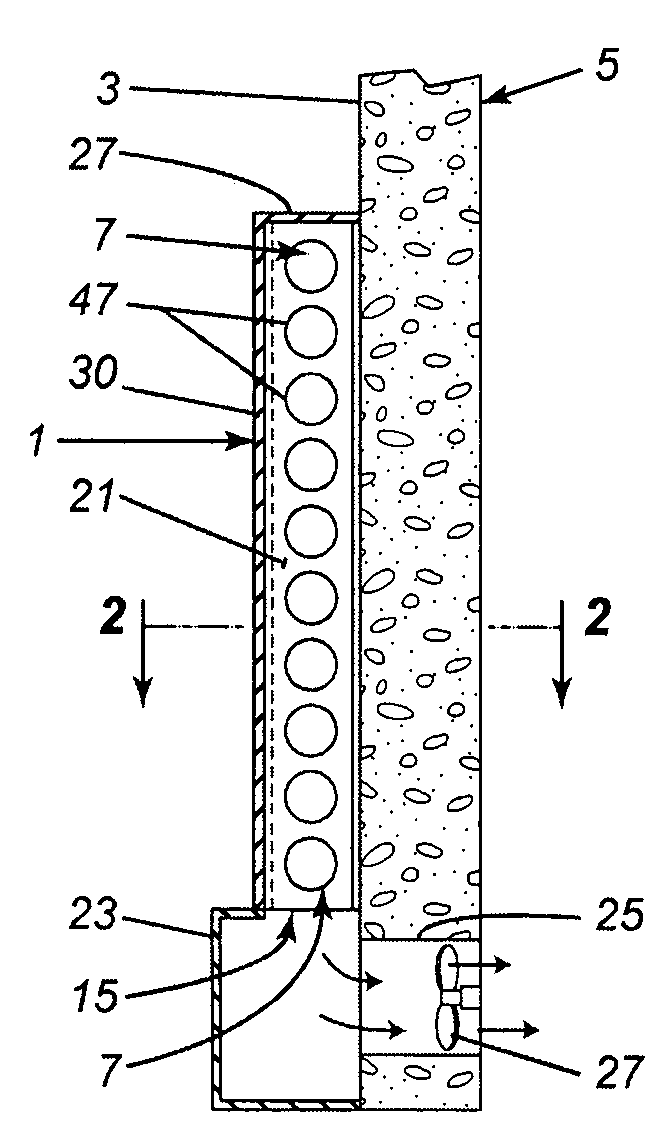
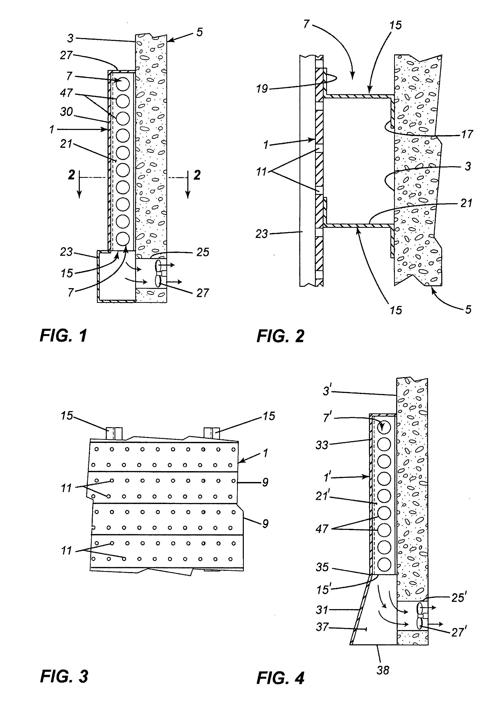
[0024]The solar air heating system, as shown in FIGS. 1-3, has a perforated, heat-absorbing panel 1 mounted on a south facing wall 3 of a building 5. The panel could be coated on its outside surface with a black paint to make it heat absorbing. The panel 1 is spaced a short distance from the wall 5 to form an air channel 7. The panel 1 can be made up of a plurality interlocked siding members 9, the siding members mounted horizontally on the building 5. The siding members 9 have circular perforations 11 therein, the perforations 11 normally equally spaced apart. The perforations 11 are about 0.0625 inches in diameter and there are about 3 to 8 perforations per square inch of panel but the size and density of perforations can vary depending on the amount of air required to be added to the building for heating or ventilation purposes.

[0025]To mount the siding members 9 horizontally to form the panel 1, a plurality of vertical frame members 15, horizontally spaced apart, are used to con...


PUM


Abstract

A solar air heating system for a building having a vertical, south-facing wall. The system has a perforated panel covering the wall. Vertical frame members fasten the panel to the wall to space the panel a short distance away from the wall and to form an air channel between the wall and panel. There is an air collecting space at the bottom of the channel, adjacent the wall. An air inlet in the wall connects the air collecting space to the interior of the building. A fan in the inlet draws outside air into the channel through the perforations in the panel, from the channel into the air collecting space, and from the air collecting space into the building through the air inlet.

Description

CROSS-REFERENCE TO RELATED APPLICATION[0001]This application claims the priority of Canadian application no. 2,559,641, filed 13 Sep. 2006, and which is incorporated herein by reference.BACKGROUND OF THE INVENTION[0002]1. Field of the Invention[0003]This invention is directed toward a solar air heating system for buildings.[0004]2. Description of the Related Art[0005]Solar air heating systems for buildings are known. The systems are used to heat ventilating air added to buildings. These known systems comprise a perforated, heat-absorbing panel mounted over at least a portion of the outside of a south-facing wall of a building, the panel spaced a short distance from the wall to form a vertical air channel between the panel and the wall. The sun heats the panel and air adjacent the outer surface of the panel. As the panel heats, it further heats the air adjacent the outer surface of the panel. The heated air rises along the panel outer surface and passes into the air channel through p...

Claims


Application Information

Patent Timeline
Patent Type & Authority Applications(United States)
IPC IPC(8): F24J2/04F24S10/50F24S90/00
CPCF24F5/0075F24F2005/0064F24J2/0444Y02B10/24Y02B30/92Y02E10/44F24F2005/0082Y02B10/20Y02A30/272F24S10/80F24S20/66Y02A30/00Y02B30/90
Inventor WILKINSON, BRIAN
Owner MATRIX ENERGY
Why Eureka
Try Eureka