As BHP increases, drilling rate will decrease, and if the BHP is allowed to increase to the point it exceeds the
fracture pressure, a formation fracture can occur.
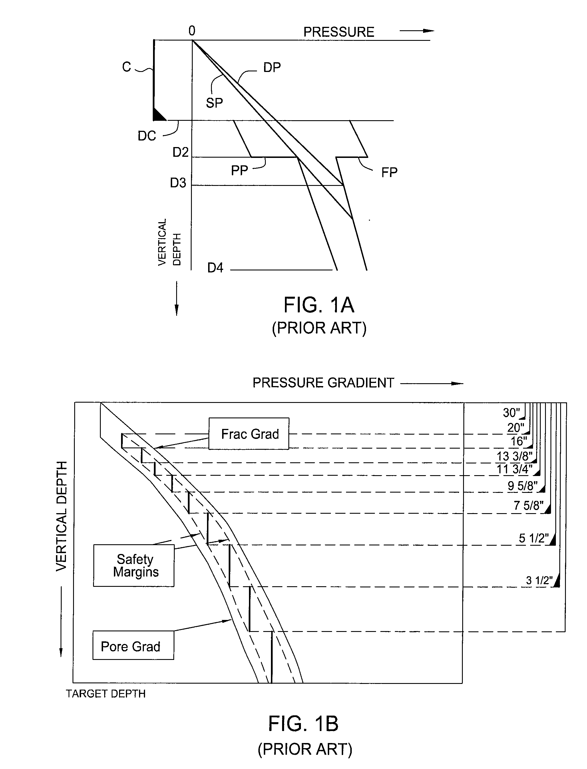
Pressures in excess of the formation
fracture pressure FP will result in the fluid pressurizing the formation walls to the extent that small cracks or fractures will open in the borehole wall and the
fluid pressure overcomes the formation pressure with significant fluid invasion.
Fluid invasion can result in reduced permeability, adversely affecting formation production.
If this fluid is not replaced, the wellbore pressure can drop and allow formation fluids to enter the wellbore, causing a kick and potentially a blowout.
At the second depth D2, the pore pressure PP increases, thereby reducing the differential between the pore pressure PP and the static pressure SP and also decreasing the
margin of safety during operations.
As noted above, while additional weighting material may be added to the fluid, it will be generally ineffective in dealing with a gas kick due to the time required to increase the
fluid density as seen in the borehole.
Recently,
oil exploration and production is moving towards more challenging environments, such as deep and ultra-deepwater.
Also, wells are now drilled in areas with increasing environmental and technical risks.
In this context, narrow windows between the pore pressure and the
fracture pressure of the formation are problematic.
It is not difficult to imagine the problems created by drilling in a narrow window, with the requirement of several casing strings, increasing tremendously the cost of the well.
Moreover, the current well design shown in FIG. 1B does not reach the required target depth for production, since the last casing size will be too small to allow for a sufficiently sized
production tubing string which will deliver oil to the surface at a sufficient flow rate to justify the cost of drilling and completing the well.
In many of these cases, the wells are abandoned, leaving the operators with huge losses.
These problems are further compounded and complicated by the density variations caused by temperature changes along the wellbore, especially in deepwater wells.
This can lead to significant problems, relative to the narrow window, when wells are shut in to detect kicks / fluid losses.
The
cooling effect and subsequent density changes can modify the annulus pressure profile due to the temperature effect on mud
viscosity, and due to the density increase leading to further complications on resuming circulation.
Thus using the conventional method for wells in ultra
deep water is rapidly reaching technical limits.
Even when using conservative overbalanced drilling techniques, the wellbore pressure may fall out of the acceptable range between pore pressure and fracture pressure and cause a kick.
Kicks may occur for reasons, such as drilling through an abnormally
high pressure formation, creating a swabbing effect when pulling the
drill string out of the well for changing a bit, not replacing the drilling fluid displaced by the
drill string when pulling the
drill string out of the hole, and, as discussed above, fluid loss into the formation.
If not properly controlled, this influx is known as a blowout and may result in the loss of the well, the drilling rig, and possibly the lives of those operating the rig.
Shutting the well in uses valuable rig time and involves a drilling stoppage, which may cause other problems, such as a stuck drill string.
One deficiency of the prior art MWD methods is that many tools transmit
pressure measurement data back to the surface on an intermittent basis.
Further, attenuation is significant for higher frequency pulses.
Mud pulse
telemetry does not work or does not work well when fluids are not being circulated, are being circulated at a
slow rate, and / or when gasified drilling fluid is used.
Therefore, mud pulse
telemetry and therefore standard MWD tools have very little utility when the well is shut in and fluid is not circulating.
Accordingly, for
deep water wells, a
subsea receiver would have to be installed at the mud line, which may not be practical.

