
Magnetic circuit and method and apparatus for the manufacture thereof

a technology of magnetic circuit and manufacturing method, applied in the direction of magnets, cores/yokes, magnetic bodies, etc., can solve the problems of compacted body, high manufacturing difficulty, and inability to form into a cylindrical permanent magnet only with great difficulty, etc., to achieve easy incorporation, low cost, and high precision.

Active Publication Date: 2008-03-13
TDK CORPARATION
View PDF4 Cites 15 Cited by
  • Summary
  • Abstract
  • Description
  • Claims
  • Application Information

AI Technical Summary

Benefits of technology

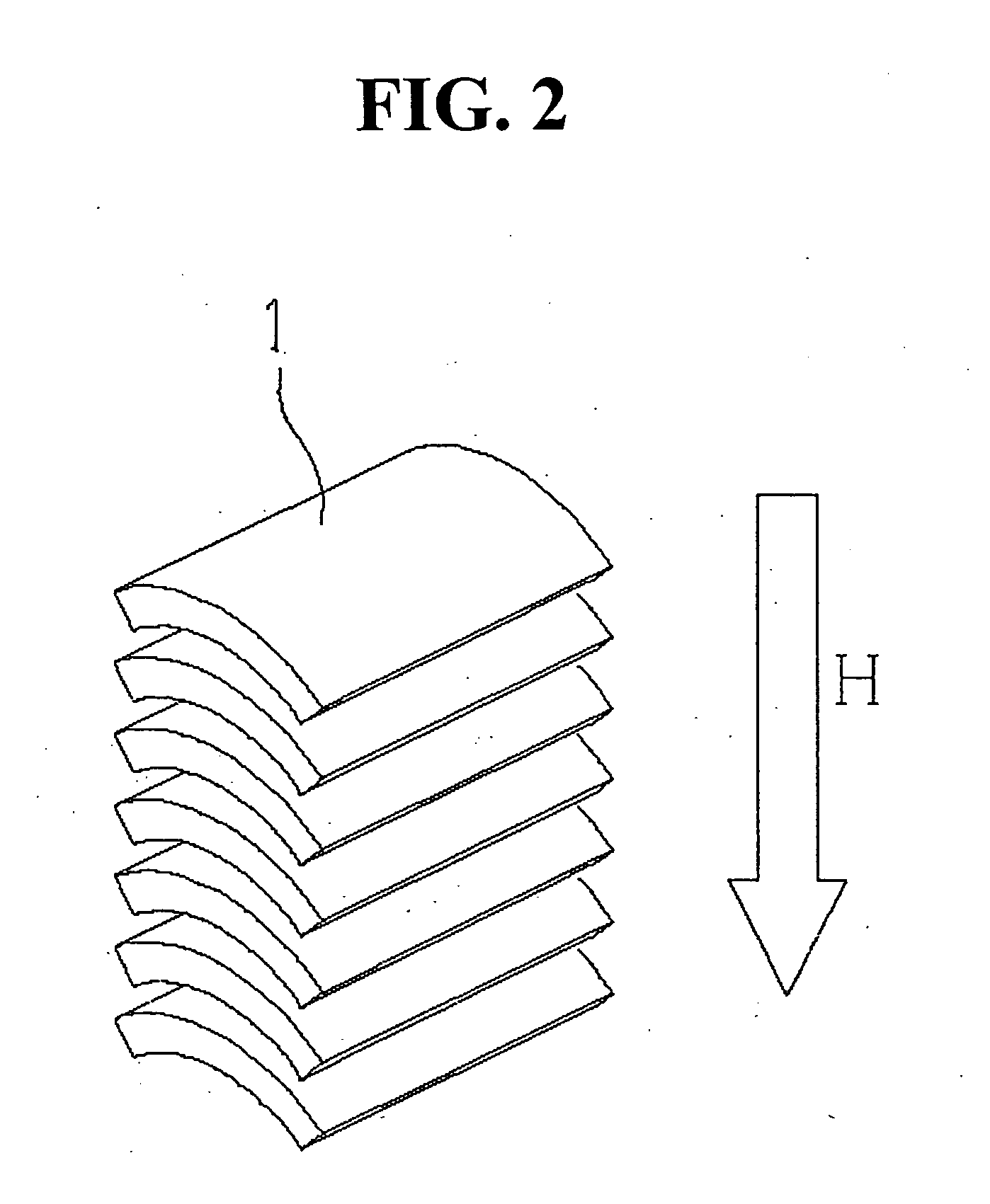
[0017]The C-shaped permanent magnet segments are easy to manufacture even in the case of using rare earth sintered magnets. Since the segments formed even in a small thickness sustain few cracks or chips during the process of sintering, they can be manufactured at high yield. Deformation thereof during the process of sintering can be suppressed to a great extent as compared with cylindrical magnets. Also, since the C-shaped permanent magnet segments can be stacked in their thickness direction, they can be magnetized in a lump to shorten the magnetization time to a great extent.
[0021]By the simple operation of the magnetic attraction of the C-shaped permanent magnet segments to the center rod and the insertion of the center rod into and extraction thereof from the yoke member, plural C-shaped permanent magnet segments can be accurately positioned and magnetically attracted and fixed to the yoke member. Therefore, insertion of the magnet segments into the yoke member can continuously be performed for a short period of time and, after the insertion, it is unnecessary to magnetize the magnet segments.
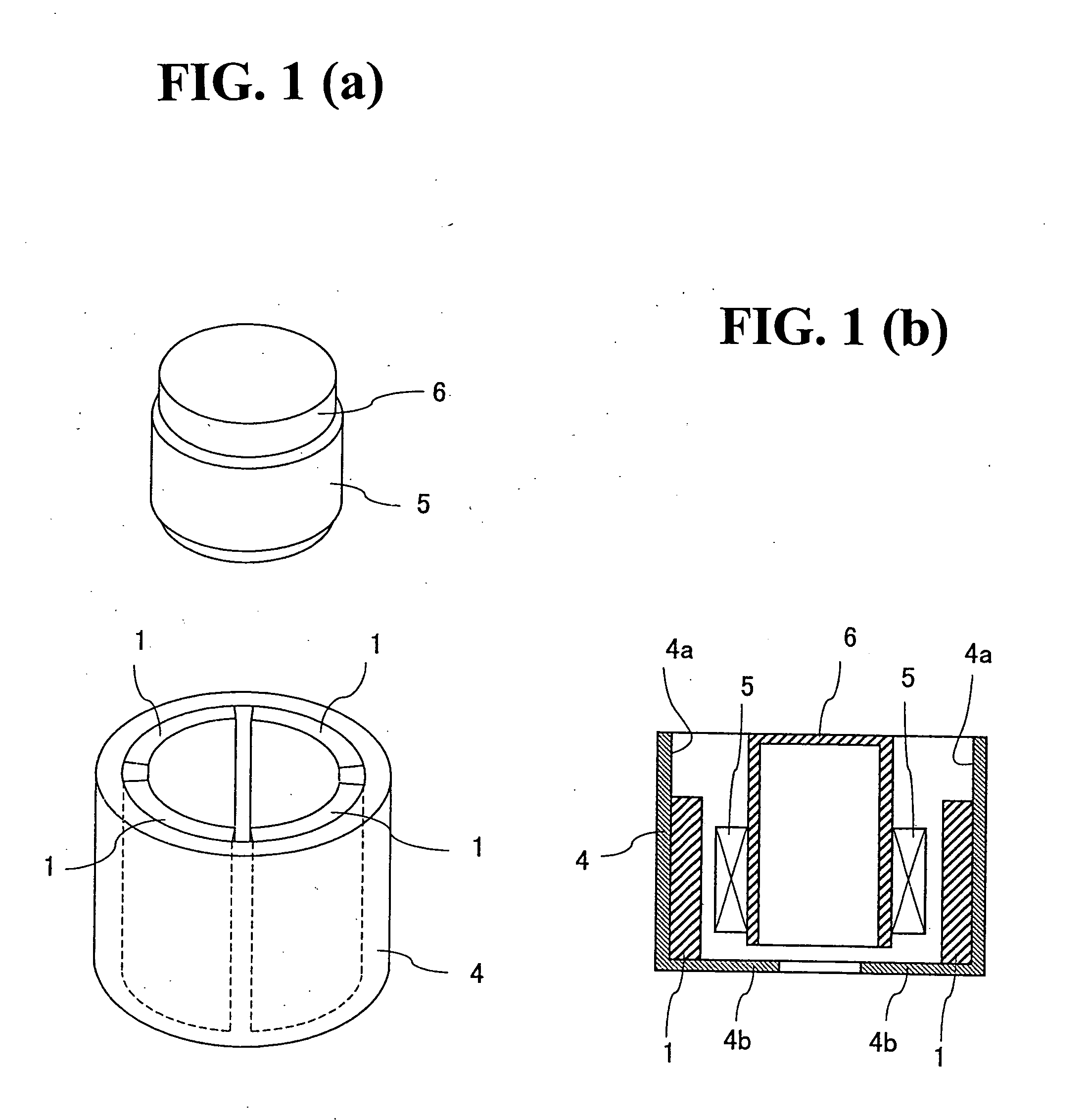
[0024]According to the magnetic circuit of the present invention, since not a cylindrical permanent magnet, but the C-shaped permanent magnet segments are incorporated, difficulty in producing a cylindrical permanent magnet, particularly a cylindrical rare earth sintered magnet, can be eliminated. Also, use of the magnetic circuit enables an inexpensive and high-performance actuator or speaker to be materialized. Furthermore, since the C-shaped permanent magnet segments are magnetically attracted to both the inner circumferential surface and the turned-back collar of the yoke member, it is made possible to fix the segments to the yoke member without use of an adhesive agent. Thus, it is possible to provide a magnetic circuit strong enough to endure vibration resulting from its fall etc at low cost.
[0025]On the other hand, according to the manufacturing method and apparatus of the present invention, since the plurally divided C-shaped permanent magnet segments can easily be incorporated into the yoke member, it is made possible to manufacture a high-performance and miniaturized magnetic circuit with high efficiency. Also, since not a cylindrical permanent magnet, but the C-shaped permanent magnet segments are incorporated, difficulty in producing a cylindrical permanent magnet, particularly a cylindrical rare earth sintered magnet, can be eliminated. Thus, it is possible to provide an inexpensive magnetic circuit with high productivity.

Problems solved by technology

Actuators using a permanent magnet have encountered problems as to how control precision is to be made high and how impellent is to be enhanced.
While each of the former and latter prior art references uses a cylindrical permanent magnet in a magnetic circuit constituting an actuator, a rare earth sintered magnet exhibiting high magnetic intensity is formed into a cylindrical permanent magnet only with great difficulty from the manufacturing point of view.
In this case, the compacted body is liable to be shrunk and deformed during the process of the sintering treatment.
When such shrinkage arises, circularity is lowered to require polishing for adjustment of the outside and inside diameters before incorporating the magnet into the actuator, thus inducing an increase in man-hour and manufacturing cost.
As a result, the force of affixing the magnet to the yoke is considerably diminished to possibly necessitate concomitant use of affixation by an adhesive.
Furthermore, a problem will arise when magnetizing the magnet.
A cylindrical rare earth sintered magnet having the radial orientation, when being formed in a small wall thickness, for example, sustains cracks or chips during the process of sintering, resulting in tendency to greatly lower the yield.
This decrease in yield constitutes a serious cause of preventing an actuator from having high performance and from being miniaturized.

Method used


Image

  • Magnetic circuit and method and apparatus for the manufacture thereof
  • Magnetic circuit and method and apparatus for the manufacture thereof
  • Magnetic circuit and method and apparatus for the manufacture thereof

Examples


Embodiment Construction

[0038]Embodiments of a magnetic circuit, its manufacturing method and apparatus, an actuator and a speaker each having the magnetic circuit incorporated therein according to the present invention will be described in detail with reference to the accompanying drawings.

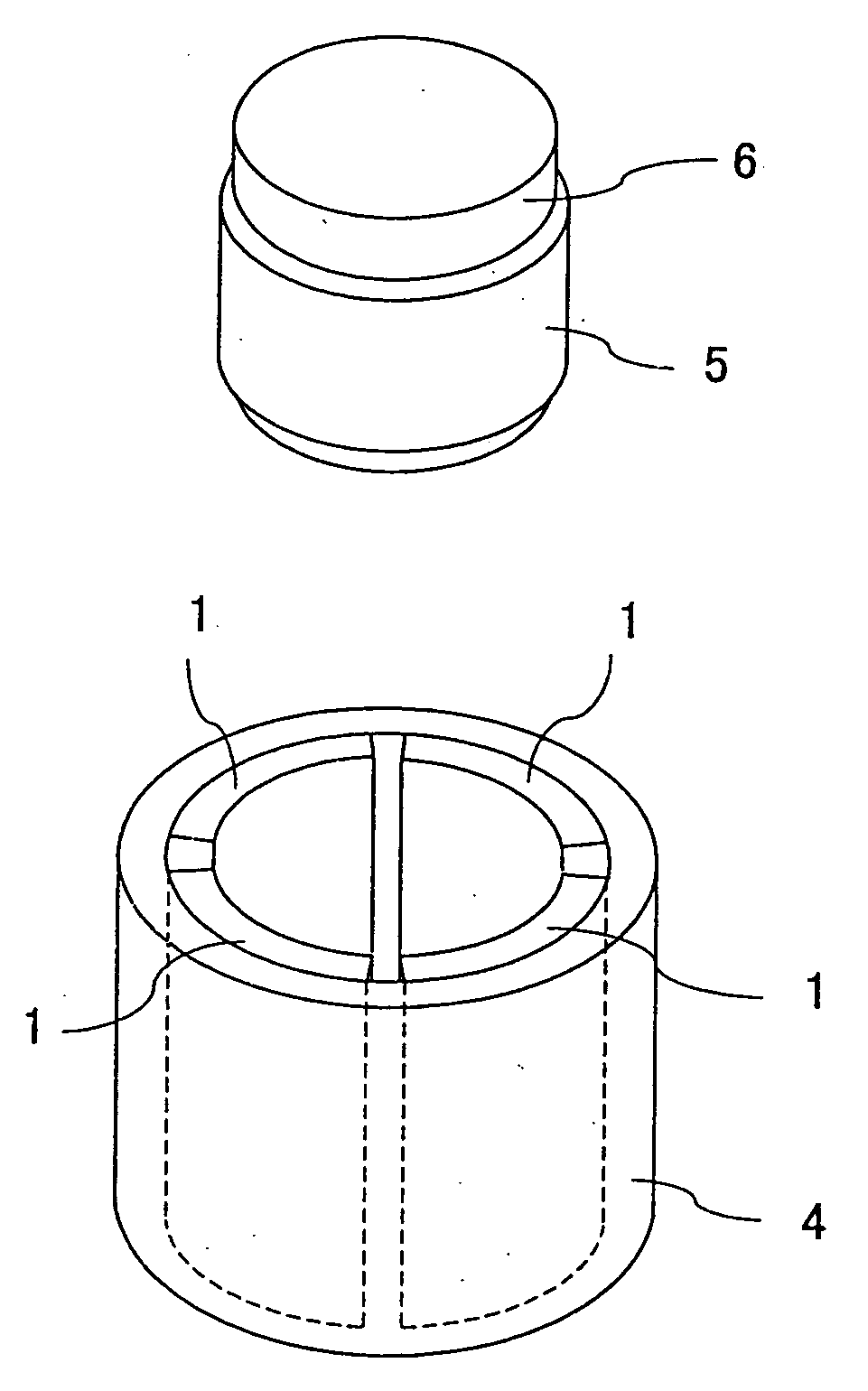
[0039]First, as regards a permanent magnet incorporated into a yoke member of a magnetic circuit, not a cylindrical shape, but segments of a shape into which the cylindrical shape is divided, i.e. permanent magnet segments having a partially circular arc in cross section (C-shaped permanent magnet segments) are used in the present invention.

[0040]The direction of orientation of the C-shaped magnet segments may be either a direction parallel to the width direction (direction substantially orthogonal to the partially circular arc cross section) thereof or a direction of the thickness thereof. When it is intended to converge the magnetic flux so as to contribute to a coil disposed at the center portion of an actuator, for ...


PUM

PropertyMeasurementUnit
Lengthaaaaaaaaaa
Lengthaaaaaaaaaa
Lengthaaaaaaaaaa

Abstract

A magnetic circuit includes a cylindrical yoke member having an inner circumferential surface and a collar formed at one end thereof and turned back substantially at right angles, and a plurality of permanent magnet segments of a partially circular arc in cross section having respective outer surfaces attracted magnetically to the inner circumferential surface of the cylindrical yoke member and respective one end faces attracted magnetically to the collar of the cylindrical yoke member. The magnetic circuit is manufactured by a method including the steps of magnetically attracting the permanent magnet segments to an outer peripheral surface of a center rod, causing the magnet segments in a magnetically attracted state to face the yoke member, using a nonmagnetic supporter to regulate the magnet segments in position, extracting the center rod from the magnet segments in a position-regulated state, and magnetically attracting and fixing the magnet segments to the yoke member. The magnetic circuit is applied to an actuator or a speaker.

Description

BACKGROUND OF THE INVENTION[0001]1. Field of the Invention[0002]The present invention relates to a magnetic circuit for use in a magnet-aided actuator for converting electric energy to kinetic energy etc. and a method and apparatus for the manufacture thereof and to an improvement in a method for incorporating a permanent magnet into a yoke member. It further relates to an actuator or speaker using the magnetic circuit.[0003]2. Description of the Prior Art[0004]For various kinds of office automation equipment, linear motors (voice coil motors), controllers, etc., for example, actuators of a variety of types have been developed. Concrete examples include an actuator having a magnetic coil and a magnetic core made movable and an actuator having a permanent magnet movable. In either case, the actuator comprises a yoke, a magnetic coil and a permanent magnet in combination.[0005]Actuators using a permanent magnet have encountered problems as to how control precision is to be made high a...

Claims


Application Information

Patent Timeline
IPC IPC(8): H02K41/00H04R17/00H04R11/02
CPCH01F7/0289H01F7/066H01F41/0253H02K15/03H02K41/0356Y10T29/49002H04R31/006H04R2209/024Y10T29/49009Y10T29/4908H04R9/025
Inventor SAITOU, SHIGEOTANAKA, MITSUTOSHIMITAKE, KOUJI
Owner TDK CORPARATION
Learn More