Switching power supply unit and control method of switching power supply unit

Inactive Publication Date: 2008-03-13
RENESAS ELECTRONICS CORP
View PDF8 Cites 35 Cited by
  • Summary
  • Abstract
  • Description
  • Claims
  • Application Information

AI Technical Summary

Benefits of technology

[0012]According to the present invention, a switching power supply unit selects a signal that switches on/off a semiconductor switch by determining whether or not the frequency of a pulse frequency modulated signal exceeds a predetermined value.

Problems solved by technology

Particularly recent electronic apparatuses operating with low voltage power supplies, for instance mobile communication terminal devices, do not have much tolerance for a decrease in power supply voltage despite the fact that the load fluctuates greatly.
In such an electronic device, the technology disclosed in Patent Document 1, in which a pulse width modulated

Method used


Image

  • Switching power supply unit and control method of switching power supply unit
  • Switching power supply unit and control method of switching power supply unit
  • Switching power supply unit and control method of switching power supply unit

Examples


example 1

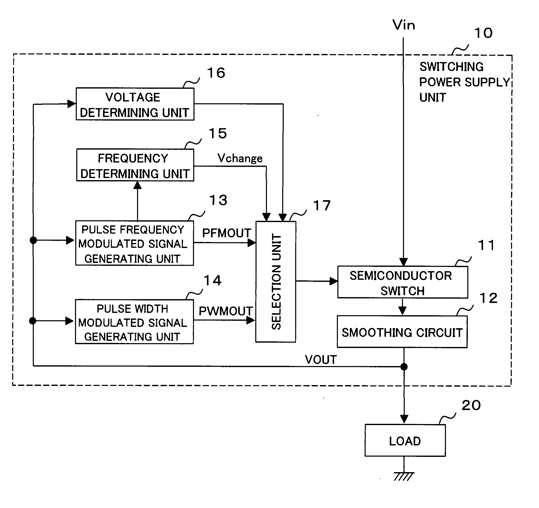
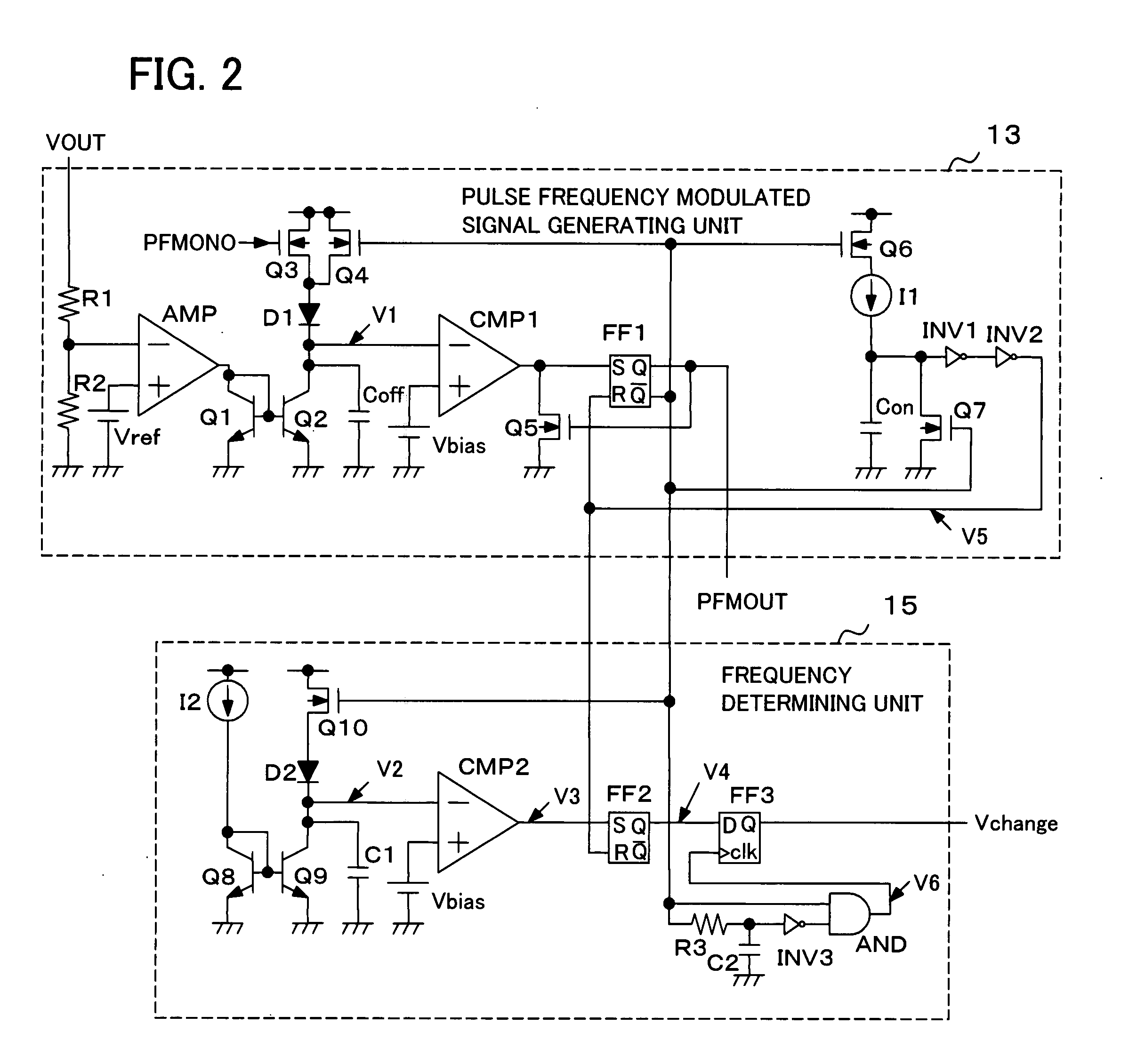
[0028]FIG. 2 is a circuit diagram of the pulse frequency modulated signal generating unit and the frequency determining unit relating to an example of the present invention. In FIG. 2, the pulse frequency modulated signal generating unit 13 comprises NPN transistors Q1 and Q2, PMOS transistors Q3, Q4, and Q6, NMOS transistors Q5 and Q7, a diode D1, an amplifier AMP, a comparator CMP1, inverter circuits INV1 and INV2, a flip-flop circuit FF1, a current source I1, resistors R1 and R2, capacitors Con and Coff, and voltage sources Vref and Vbias.

[0029]The amplifier AMP amplifies a difference between a voltage obtained by having the serially-connected resistors R1 and R2 divide the voltage VOUT at the load and a voltage at the voltage source Vref, and supplies the amplified result to a current mirror constituted by the NPN transistors Q1 and Q2. While one end of the capacitor Coff is grounded, a voltage V1 at the other end is rapidly charged from the PMOS transistor Q4 via the diode D1 w...


PUM


Abstract

Decrease in a voltage supplied to a load caused by load fluctuations is minimized. A pulse frequency modulated signal generating unit 13 outputs a signal PFMOUT having a pulse frequency modulated according to a voltage supplied to the load 20. A pulse width modulated signal generating unit 14 outputs a signal PWMOUT having a pulse width modulated according to a voltage supplied to the load 20. In a state where the signal PFMOUT is selected, a selection unit 17 refers to a determination result of a frequency determining unit 15 and selects the signal PWMOUT as on/off signal for a semiconductor switch 11 when a low-level period in one cycle of the signal PFMOUT is not more than a predetermined time period. In a state where the signal PWMOUT is selected, the selection unit 17 selects the signal PFMOUT as on/off signal for the semiconductor switch 11 when a voltage determining unit 16 detects that a DC voltage (VOUT) at the load 20 exceeds a predetermined voltage.

Description

REFERENCE TO RELATED APPLICATIONS[0001]The present application is claiming the priority of the earlier Japanese patent application No. 2006-242813 filed on Sep. 07, 2006, the entire disclosure thereof being incorporated herein by reference thereto.FIELD OF THE INVENTION[0002]The present invention relates to a switching power supply unit and control method of a switching power supply unit, and particularly to a switching power supply unit and control method that perform switching using a pulse width modulated signal and a pulse frequency modulated signal.BACKGROUND OF THE INVENTION[0003]Switching power supply units, also known as DC-DC converters, are widely used in various electric and electronic apparatuses. Stability in output voltage against a wide range of input voltage and load fluctuations is often demanded from such switching power supply units. Power supply units that select either a pulse width modulated signal or a pulse frequency modulated signal during switching operatio...

Claims


Application Information

Patent Timeline
IPC IPC(8): H02M3/155G05F1/46
CPCH02M3/156
Inventor HIBI, YASUHIRO
Owner RENESAS ELECTRONICS CORP
Why Eureka
Try Eureka