
Silicon condenser microphone

a condenser microphone and condenser technology, applied in the direction of piezoelectric/electrostrictive transducers, loudspeakers, semiconductor electrostatic transducers, etc., can solve the problems of affecting the sound quality of the sound

Inactive Publication Date: 2008-03-13
BSE CO LTD
View PDF6 Cites 40 Cited by
  • Summary
  • Abstract
  • Description
  • Claims
  • Application Information

AI Technical Summary

Benefits of technology

[0008]An object of the present invention is to provide a silicon condenser microphone using a case which can be molded and a plating layer which is formed on a body formed of resin so as to prevent electromagnetic waves from being received from the outside.

Problems solved by technology

The quality of sound can be poor when sound pressure is conveyed between the case and the PCB if the pressing force applied during the curling process is weak.
On the other hand, a curling surface tears or modification of internal components occurs to falsify acoustic sound characteristics when the pressing force applied during the curling procedure is excessive.
However, since the case used in the typical condenser microphone is formed in a cylindrical shape or a rectangular box shape and formed of a metal, molding becomes difficult.

Method used


Image

  • Silicon condenser microphone
  • Silicon condenser microphone
  • Silicon condenser microphone

Examples


Embodiment Construction

[0023]Reference will now be made in detail to the preferred embodiments of the present invention, examples of which are illustrated in the accompanying drawings. Wherever possible, the same reference numbers will be used throughout the drawings to refer to the same or like parts.

[0024]Hereinafter, the present invention will be described in detail with reference to the accompanying drawings.

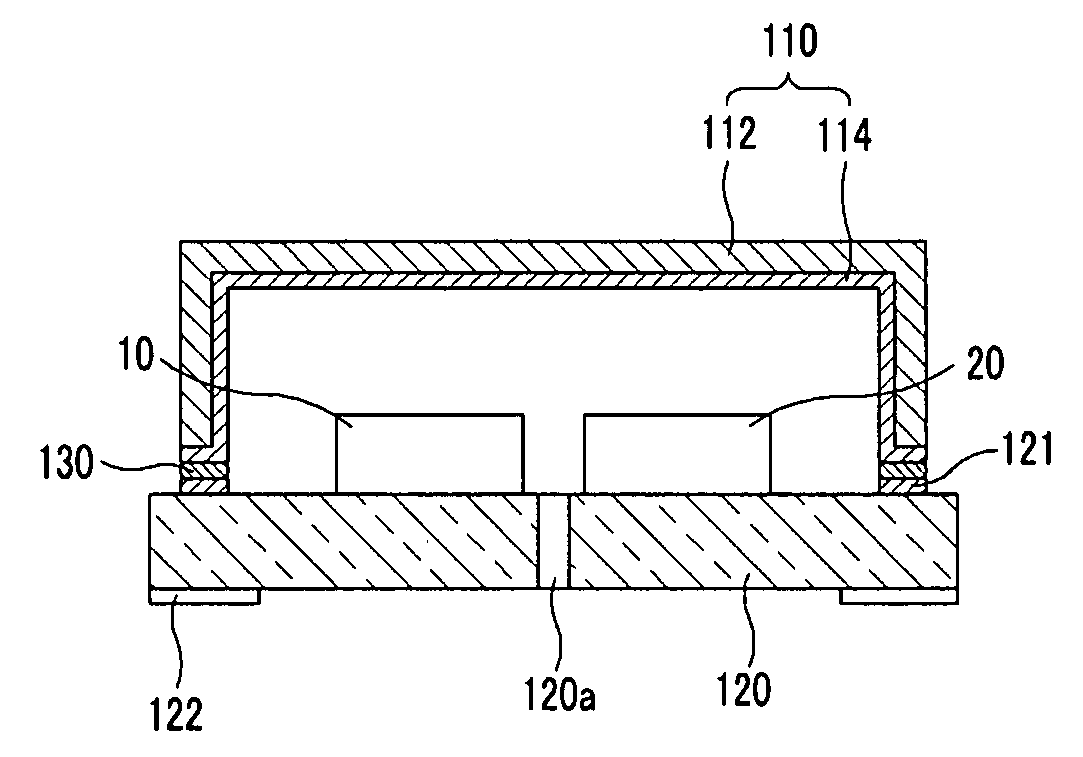
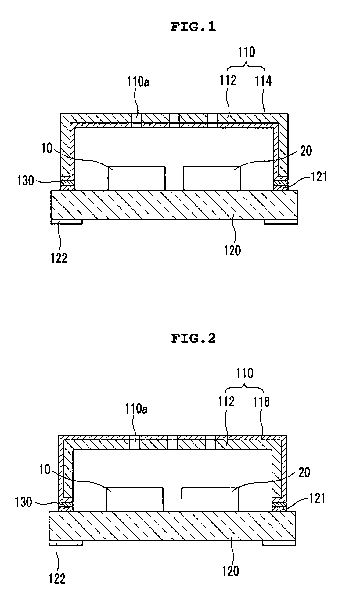
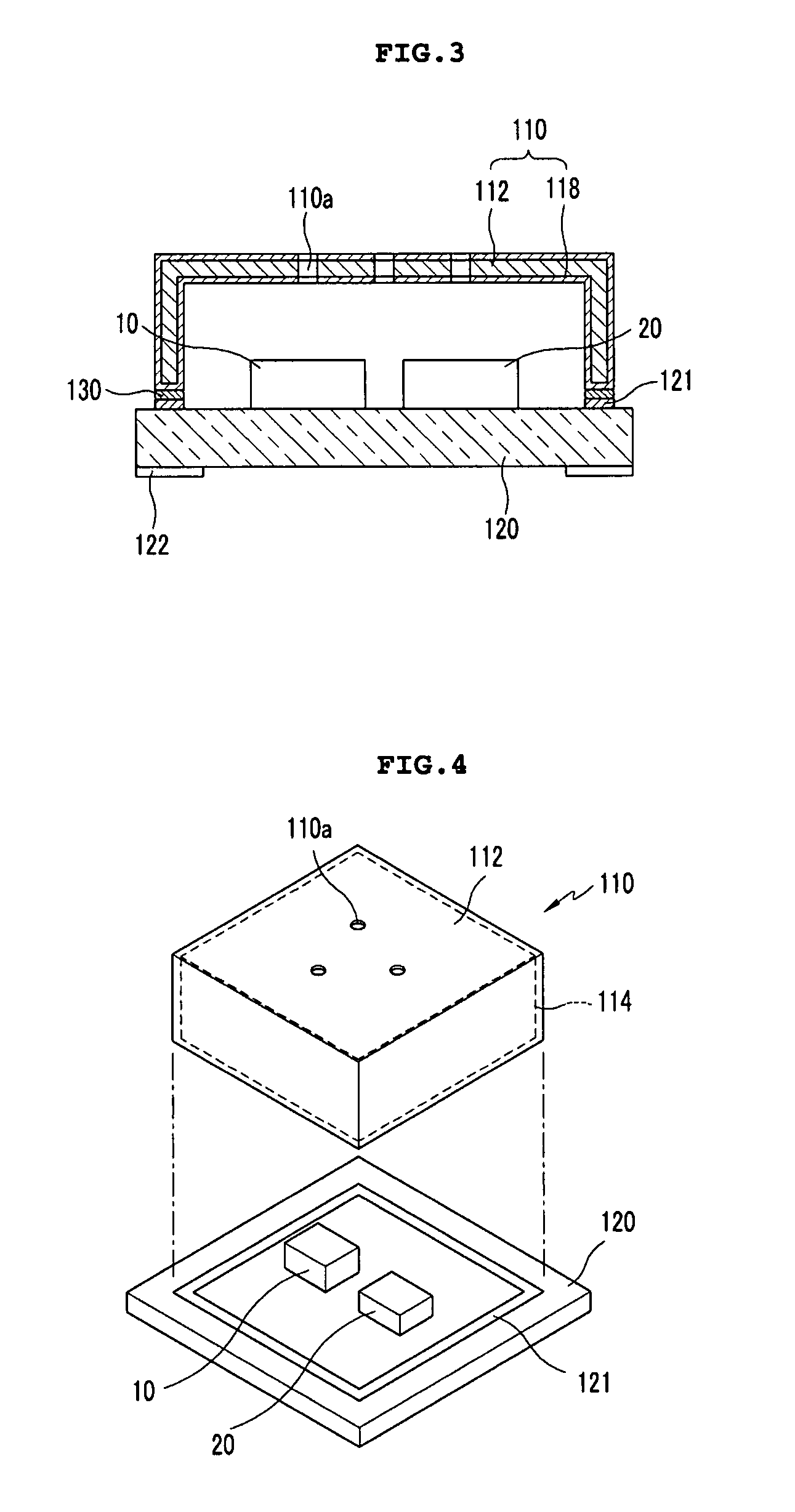
[0025]FIG. 1 is a cross-sectional view of a silicon condenser microphone in which a plating layer is formed on an inner surface of a case 110 according to an embodiment of the present invention, FIG. 2 is a cross-sectional view of a silicon condenser microphone in which a plating layer is formed on an outer surface of the case according to an embodiment of the present invention, and FIG. 3 is a cross-sectional view of a silicon condenser microphone in which a plating layer is formed on an entire surface of the case according to an embodiment of the present invention.

[0026]Referring to FIGS. 1 to 3...


PUM


Abstract

Provided is a silicon condenser microphone using a case in which a plating layer is formed on a body formed of resin. The silicon condenser microphone includes: a case having a can-shaped resin body with one side open, and a plating layer formed on the body; and a substrate on which a micro electro mechanical system (MEMS) microphone chip and an application-specific integrated circuit (ASIC) chip for processing an electrical signal are mounted, a connection pattern for attaching the case is formed, and the case is attached to the connection pattern using a conductive adhesive. The case may be formed in a cylindrical shape or a rectangular box shape. The plating layer may be formed on an inner surface, an outer surface, or an entire surface of the body and a step may be formed along an inner periphery on an end portion of an opening surface of the body.

Description

BACKGROUND OF THE INVENTION[0001]1. Field of the Invention[0002]The present invention relates to a silicon condenser microphone, and more particularly, to a silicon condenser microphone using a case in which a plating layer is formed on a case body formed of resin.[0003]2. Description of the Related Art[0004]Condenser microphones are widely used in mobile communication terminals, audio equipment, etc. A typical condenser microphone includes a voltage bias element, a diaphragm / backplate pair configured to form a capacitance varying with a sound pressure, and a junction field effect transistor (JFET) configured to buffer an output signal. Such a typical condenser microphone is fabricated by assembling a diaphragm, a spacer ring, an insulating ring, a backplate, a conductive ring, and a printed circuit board (PCB) within a case, and curling an edge portion of the case.[0005]A curling process is to curl the edge portion of the case with applying a pressure toward the PCB. The curling pr...

Claims


Application Information

Patent Timeline
IPC IPC(8): H04R9/08
CPCH04R19/005H04R19/04H04R2400/11H04R2201/34H04R31/006H04R1/02H04R1/06H04R2201/02
Inventor SONG, CHUNG DAM
Owner BSE CO LTD
Learn More