Method for Manufacturing an Optical Preform

a manufacturing method and optical preform technology, applied in the field of optical preform manufacturing, can solve the problems of increasing pressure in the tube, reducing and removing soot particles instead of glass, so as to improve the efficiency of glass deposition

Inactive Publication Date: 2008-03-13
DRAKA COMTEQ BV
View PDF6 Cites 16 Cited by
  • Summary
  • Abstract
  • Description
  • Claims
  • Application Information

AI Technical Summary

Benefits of technology

[0007]It is an object of the present invention to provide

Problems solved by technology

This, however, causes the pressure in the tube to increase, which may lead to the deposition of so-called soot particles instead of glass.
This publication further explains that increasing the mass flow rate of the glass-forming precursors may also lead to the

Method used


Image

  • Method for Manufacturing an Optical Preform
  • Method for Manufacturing an Optical Preform

Examples


Embodiment Construction

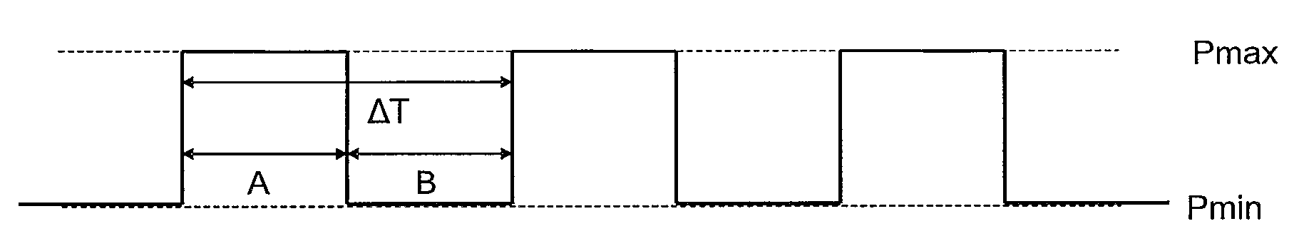
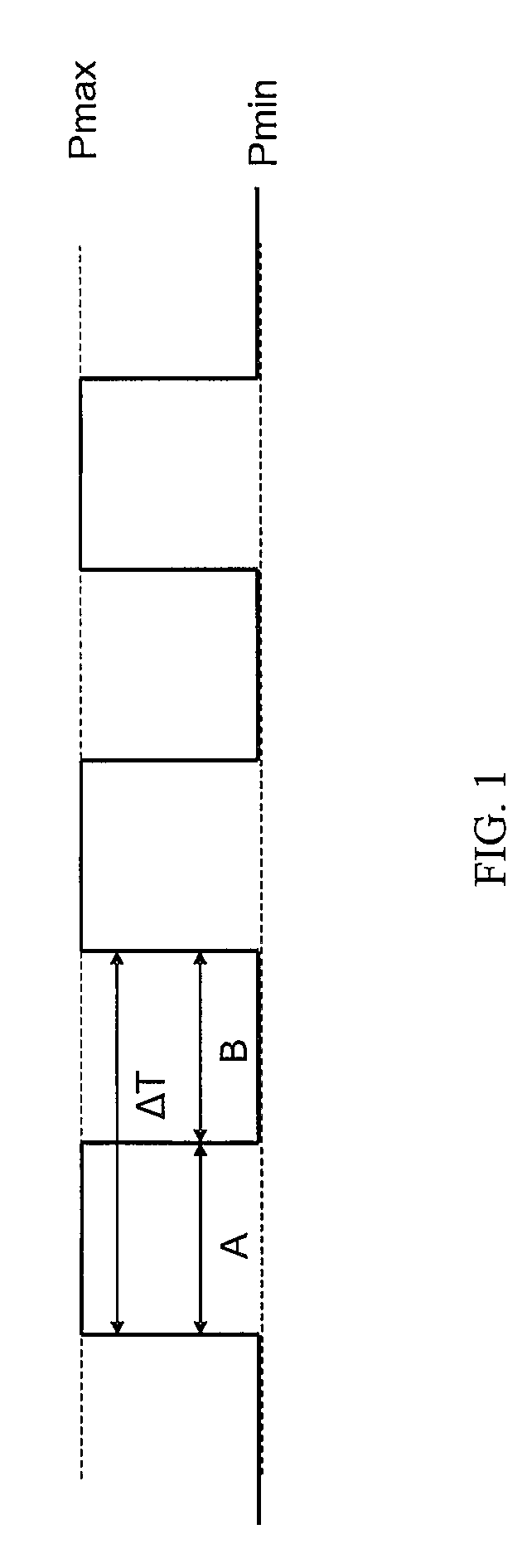
[0013]Accordingly, the present invention provides an improved method for manufacturing an optical preform by carrying out one or more chemical vapor deposition reactions in a substrate tube by (i) supplying one or more doped or undoped glass-forming precursors (i.e., the reactants) to a substrate tube and (ii) effecting a reaction between these reactants to form one or more glass layers on the interior of the substrate tube via the creation of only a pulsed plasma zone in the interior of the substrate tube. This pulsed plasma zone is realized in pulses, typically using a frequency at least 100 Hz, with a maximum plasma power being active each pulse cycle for a period of between 0.001 and 5 milliseconds. In certain embodiments, the pulse frequency is at least 1500 Hz.

[0014]The present inventors have found that when high deposition rates are sought at increased microwave power, a considerable part of the microwave energy is eventually converted into heat. This can lead to overheating ...


PUM

PropertyMeasurementUnit
Fractionaaaaaaaaaa
Fractionaaaaaaaaaa
Fractionaaaaaaaaaa

Abstract

The present invention relates to a method for manufacturing an optical preform by carrying out one or more chemical vapor deposition reactions in a substrate tube. The method includes the steps of (i) supplying one or more doped or undoped glass-forming precursors to a substrate tube and (ii) effecting a reaction between these glass-forming precursors to form one or more glass layers on the interior of the substrate tube via the creation of a pulsed plasma zone in the interior of the substrate tube.

Description

CROSS-REFERENCE TO PRIORITY APPLICATION[0001]This application claims the benefit of pending Dutch Application No. 1,032,463 (filed Sep. 8, 2006, at the Dutch Patent Office), which is hereby incorporated by reference in its entirety.FIELD OF THE INVENTION[0002]The present invention relates to an improved method for manufacturing an optical preform by carrying out one or more chemical vapor deposition reactions in a substrate tube.BACKGROUND OF THE INVENTION[0003]Chemical vapor deposition (CVD) and plasma chemical vapor deposition (PCVD) are known in the art.[0004]For example, International Publication No. WO 03 / 057635 mentions as a PCVD shortcoming the low glass-deposition rate, and explains that one way to increase the deposition rate is to increase the mass flow rate of the glass-forming precursors in the interior of the substrate tube. This, however, causes the pressure in the tube to increase, which may lead to the deposition of so-called soot particles instead of glass. This pub...

Claims


Application Information

Patent Timeline
IPC IPC(8): H05H1/24
CPCC03B37/0183
Inventor DECKERS, ROB HUBERTUS MATHEUSVAN STRALEN, MATTHEUS JACOBUS NICOLAASHARTSUIKER, JOHANNES ANTOON
Owner DRAKA COMTEQ BV
Why Eureka
Try Eureka