
Electromyography system

a technology of electromyography and nerve detection, applied in the field of electromyography, can solve the problems of increasing the danger of inadvertent contact and/or severing of the nerve of the patient, difficult to avoid inadvertent contact with the nerve, and reducing the visibility of the patient's tissues, so as to improve the accuracy of nerve detection warnings, reduce the risk of nerve contact, and improve the likelihood of nerve conta

Inactive Publication Date: 2008-03-13
NUVASIVE
View PDF44 Cites 230 Cited by
  • Summary
  • Abstract
  • Description
  • Claims
  • Application Information

AI Technical Summary

Benefits of technology

[0021] In an additional aspect of the invention, the relative neuro-muscular response onset values can be repeatedly re-determined (at automatic intervals or at intervals determined by the operator) so as to account for any changes to the response onset values caused by the surgical procedure itself. Accordingly, a further advantage of the present invention is that it permits automatic re-assessment of the nerve status, with the relative neuro-muscular response onset values for each of the plurality of spinal nerves being re-determined before, during and after the surgical procedure, or repeatedly determined again and again during the surgical procedure. This optional aspect is advantageous during spinal surgery as the surgery itself may change the relative neuro-muscular response onset values for each of the plurality of nerves, such as would be caused by reducing the pressure on an exiting spinal nerve positioned between two adjacent vertebrae. This periodic re-determination of the onset values can be carried out concurrently with the nerve sensing function.
[0022] Accordingly, an advantageous feature of the present invention is that it can simultaneously indicate to an operator both: (1) nerve detection (i.e.: whether the surgical tool / probe is near a nerve); and (2) nerve status changes (i.e.: the change in each nerve's neuro-muscular response onset values over time). The surgeon is thus able to better interpret the accuracy of nerve detection warnings by simultaneously viewing changes in the various onset levels. For example, should the surgeon note that a particular onset value (i.e.: the current level of a stimulus pulse required to elicit an EMG response for a particular nerve) is increasing, this would tend to show that this nerve pathway is becoming less sensitive. Accordingly, a “low” warning may be interpreted to more accurately correspond to a “medium” likelihood of nerve contact; or a “medium” warning may be interpreted to more accurately correspond to a “high” likelihood of nerve contact.
[0023] Optionally, such re-assessment of the nerve status can be used to automatically re-calibrate the present nerve detection system. This can be accomplished by continually updating the onset values that are then used in the nerve detection function.
[0024] In preferred aspects, the neuro-muscular response onset values for each of the plurality of spinal nerves are measured at each of the spaced-apart myotome locations, and are visually indicated to an operator (for example, by way of an LED scale). Most preferably, the measuring of each of the various neuro-muscular response onset values is repeatedly carried out with the present and previously measured onset value levels being simultaneously visually indicated to an operator such as by way of the LED scale.
[0025] Accordingly, in one preferred aspect, for example, different LED lights can be used to indicate whether the value of each of the various neuro-muscular response onset values is remaining constant over time, increasing or decreasing. An advantage of this optional feature of the invention is that a surgeon operating the device can be quickly alerted to the fact that a neuro-muscular response onset value of one or more of the spinal nerves has changed. Should the onset value decrease for a particular nerve, this may indicate that the nerve was previously compressed or impaired, but become uncompressed or no longer impaired.
[0026] In a particular preferred embodiment, example, a blue LED can be emitted at a baseline value (i.e.: when the neuro-muscular response onset value remains the same as previously measured); and a yellow light can be emitted when the neuro-muscular response onset value has increased from that previously measured; and a green light being emitted when the neuro-muscular response onset value has decreased from that previously measured.

Problems solved by technology

However, avoiding inadvertent contact with these nerves is especially difficult due to the high nerve density in the region of the spine and cauda equina.
Unfortunately, a downside of such minimally invasive surgical procedures is that they tend to offer a somewhat reduced visibility of the patient's tissues during the surgery.
Accordingly, the danger of inadvertently contacting and / or severing a patient's nerves can be increased.
However, such systems cannot be used when initially penetrating into the tissue.
Moreover, such optical viewing systems cannot reliably be used to detect the location of small diameter peripheral nerves.
A disadvantage of such systems is that they rely on a visual indication, being seen as a “twitch” in the patient's body.
During precision minimally invasive surgery, uncontrollable patient movement caused by patient twitching, is not at all desirable, since such movement may itself be injurious.
Accordingly, such systems are quite limited, and are not particularly well adapted for use in minimally invasive surgery.

Method used


Image

  • Electromyography system
  • Electromyography system
  • Electromyography system

Examples


Embodiment Construction

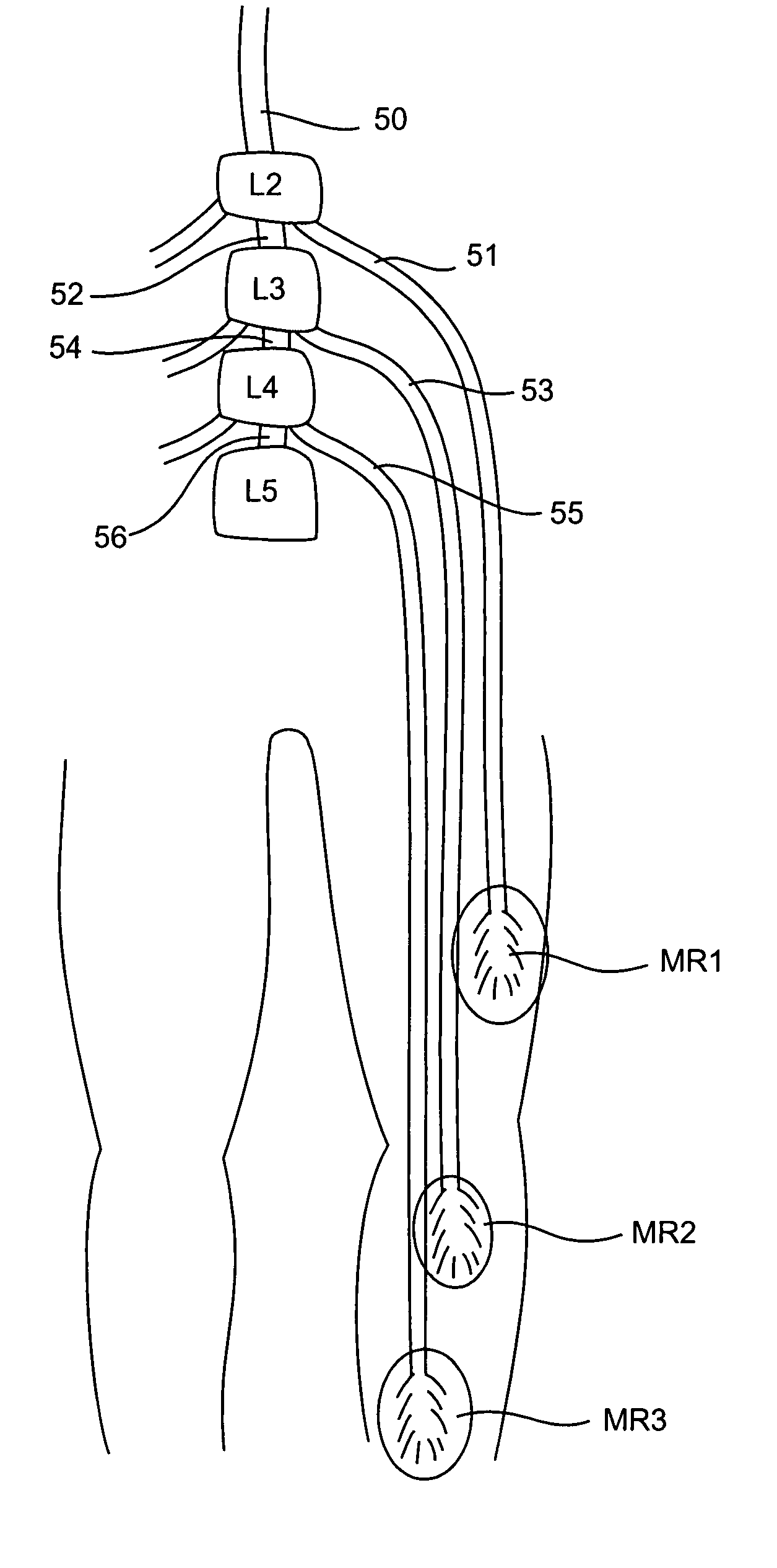
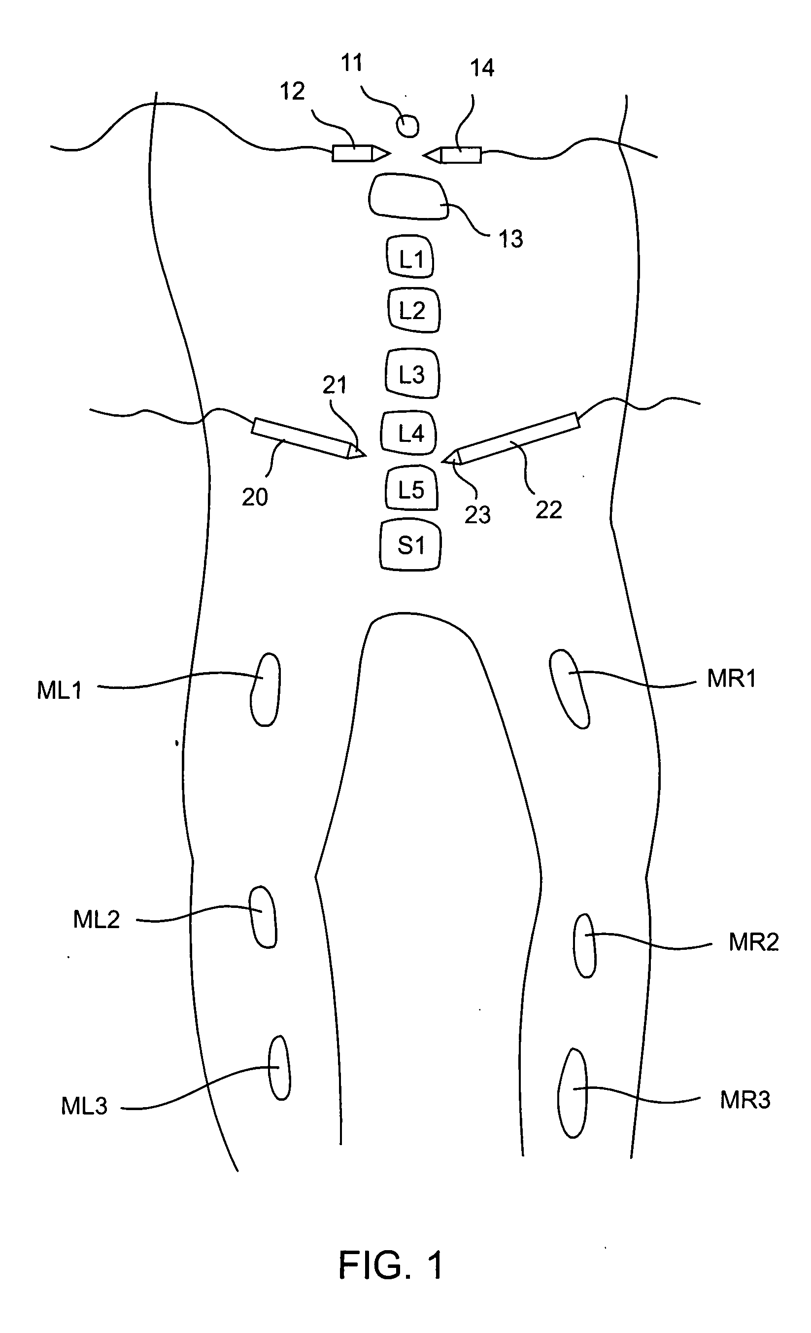
[0047] The present invention sets forth systems for detecting when a nerve is near or adjacent to an electrified surgical tool, probe, cannula, or other surgical instrument. The present invention also involves optional systems for simultaneously determining the “status” (e.g.: sensitivity) of a plurality of nerves.

[0048] As will be explained, the present system involves applying a signal with a current level to a probe near a nerve and determining whether an electromyographic “EMG” (i.e.: neuro-muscular) response for a muscle coupled to the nerve is present.

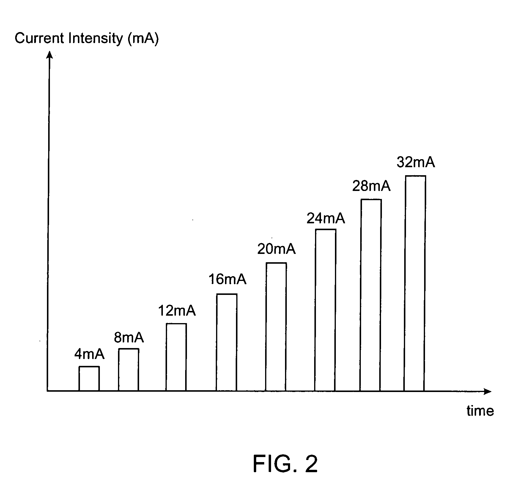
[0049] In preferred aspects, the present system applies a signal with a known current level (mA) to a “probe” (which could be midline probe, a cannula, a needle, etc.) Depending on the current level, distance to the nerve, and health of the nerve, an EMG may be detected in a muscle coupled to the nerve. In accordance with preferred aspects, an EMG response is determined to have been detected when the peak-to-peak response of th...


PUM


Abstract

Systems for determining structural integrity of a bone within the spine of a patient, the bone having a first aspect and a second aspect, wherein the second aspect separated from the first aspect by a width and located adjacent to a spinal nerve. A stimulator is configured to generate an electrical stimulus to be applied to the first aspect of the bone. A monitor is configured to electrically monitor a muscle myotome associated with the spinal nerve to detect if an onset neuro-muscular response occurs in response to the application of the electrical stimulus to the first aspect of the bone. An adjuster is configured to automatically increase the magnitude of the electrical stimulus to until the onset neuro-muscular response is detected. Lastly, a communicator is configured to communicate to a user via at least one of visual and audible means information representing the magnitude of the electrical stimulus which caused the onset neuro-muscular response.

Description

CROSS-REFERENCES TO RELATED APPLICATIONS [0001] The present application claims priority from commonly owned and co-pending U.S. patent application Ser. No. 10 / 830,189 filed Apr. 21, 2004, which claimed priority from commonly owned and co-pending U.S. patent application Ser. No. 09 / 722,070 filed Nov. 24, 2000, the complete disclosures of which are hereby incorporated herein by reference in their entirety for all purposes. Additionally, the present application claims benefit under 35 U.S.C. §119(e) from U.S. Provisional Application Ser. No. 60 / 167,416 filed Nov. 24, 1999, the entire contents of which are hereby expressly incorporated by reference into this disclosure as if set forth fully herein.TECHNICAL FIELD [0002] The present invention relates to electromyography (EMG) and to systems for detecting the presence of nerves during surgical procedures. BACKGROUND OF THE INVENTION [0003] It is important to avoid unintentionally contacting a patient's nerves when performing surgical proc...

Claims


Application Information

Patent Timeline
Patent Type & Authority Applications(United States)
IPC IPC(8): A61B5/05A61B5/04A61B5/296A61B17/00A61B19/00
CPCA61B5/04001A61B5/0488A61B5/0492A61N1/08A61B2017/00022A61B2017/00039A61B5/4893A61B5/24A61B5/296A61B5/389A61B5/4836A61B17/00234
Inventor KELLEHER, BRIAN S.MARINO, JAMES F.STONE, CORBETT W.VAUGHN, ROBIN H.OWENS, JEFFREY H.
Owner NUVASIVE
Learn More