
Computerized numerical control system with human interface using low cost shared memory

a computerized numerical control and shared memory technology, applied in computing, electric digital data processing, instruments, etc., can solve problems such as loss of real time communication between processors b>, motor drivers, and errors during controlling motor motion, and achieve the effect of low cos

Inactive Publication Date: 2008-03-13
SODICK AMERICA CORP +1
View PDF8 Cites 15 Cited by
  • Summary
  • Abstract
  • Description
  • Claims
  • Application Information

AI Technical Summary

Benefits of technology

[0007]An object of the present invention is to provide a computerized numerical control system in which communications between a numerical control device and motor drivers will not be halted while a human interface computer reads feedback data from or writes instruction data to the shared memory.
[0008]Another object of the present invention is to provide a computerized numerical control system which eliminates the use of expensive Dual Port RAM.
[0009]Yet another object of the present invention is to provide a computerized numerical control system which allows fast and massive data transfer at low cost.
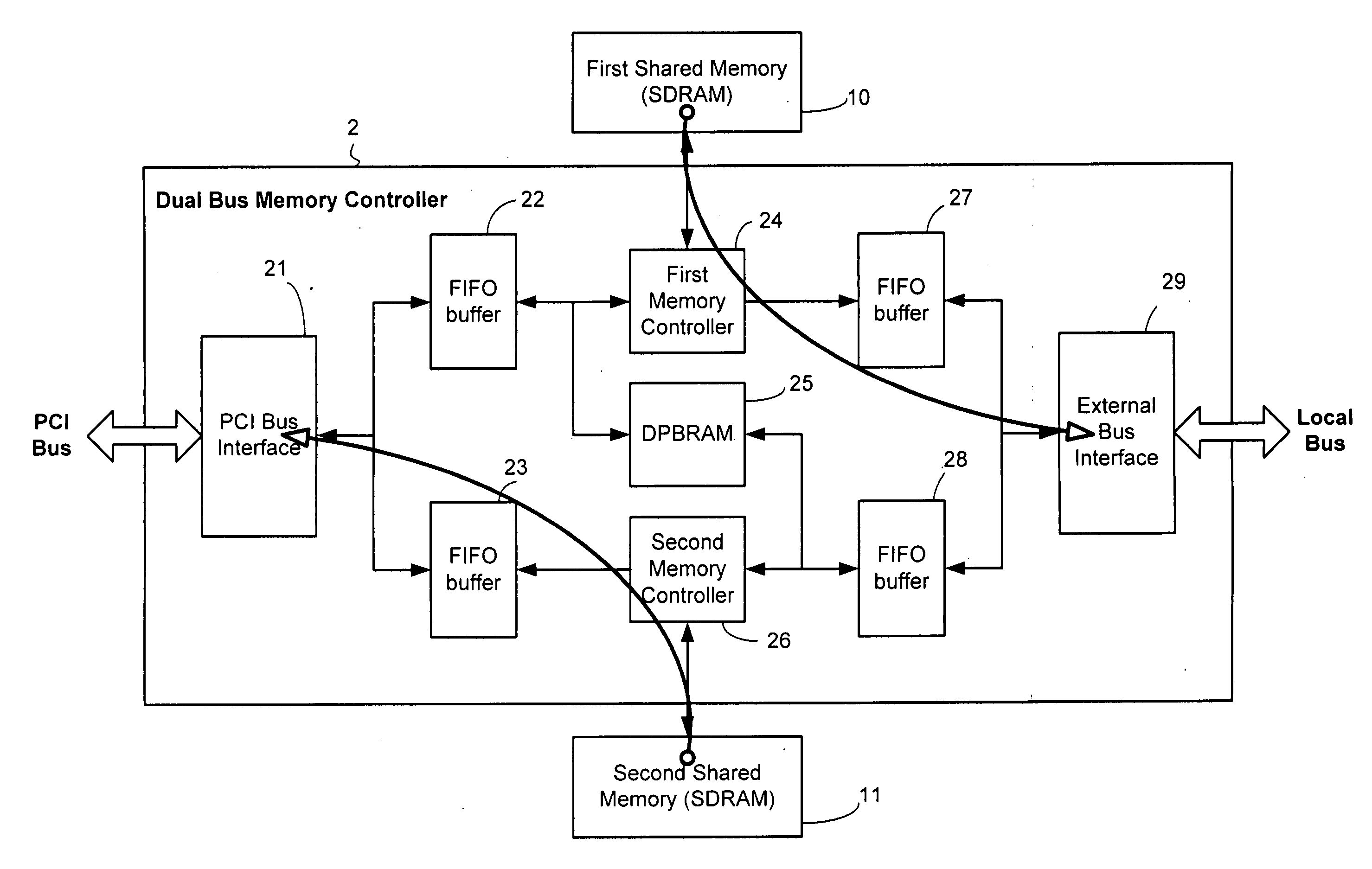
[0017]It is preferable that the dual bus memory controller is implemented in hardware description language using FPGA and that each of the first and second shared memories is a low cost SDR SDRAM or DDR SDRAM.

Problems solved by technology

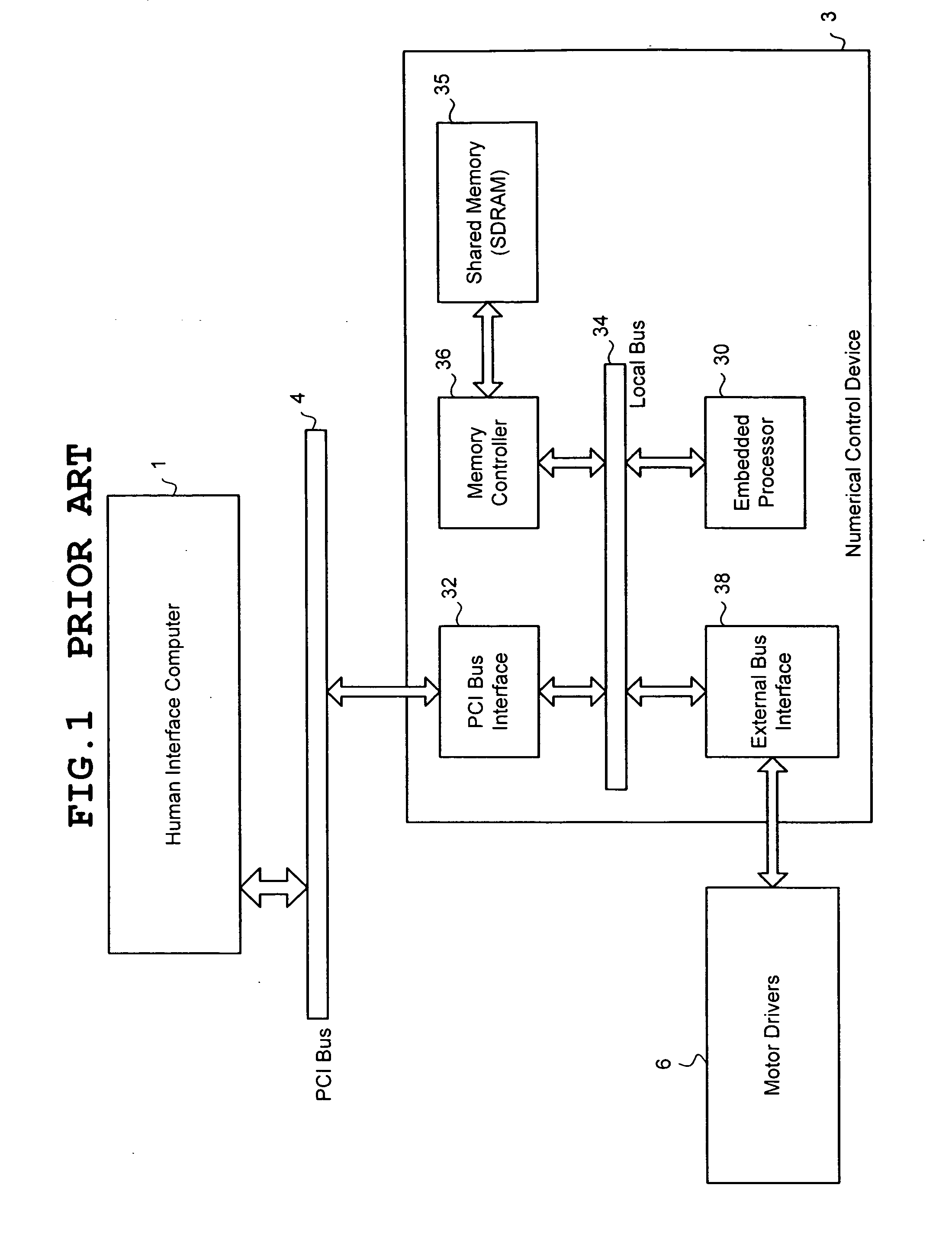
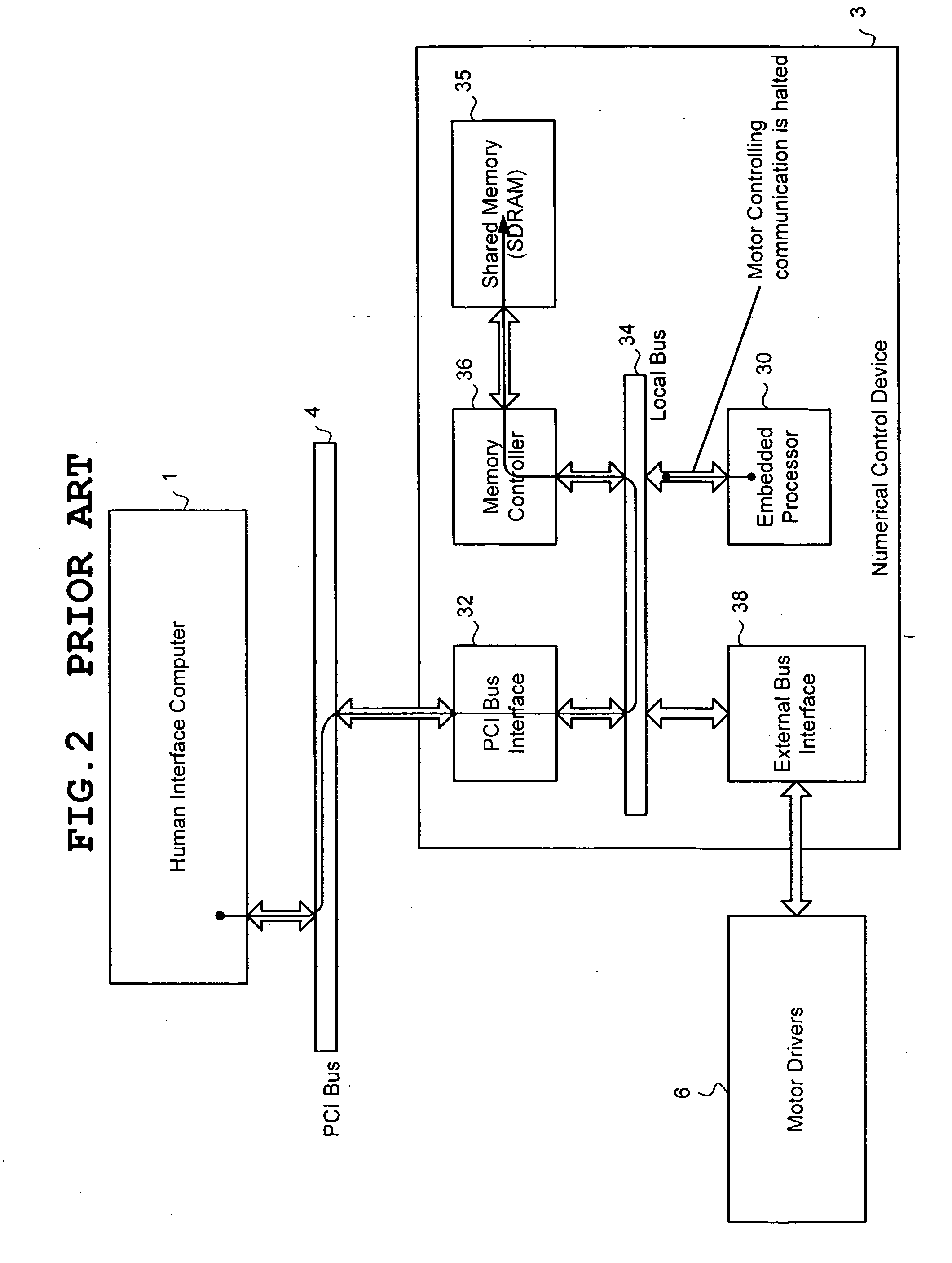
There is a serious problem in this conventional technology.
This results in lost of real time communication between the processor 30 and motor drivers 6.
It is likely to lead to error during controlling motor's motion, as shown in FIG. 2.
Or, phase cycle time need to be increased which reduces the performance of motor's motion control.
The conventional architecture is not good enough to provide high performance in a computerized numeric control system.
Although this conventional design has solved the above described problem, the cost of production is drastically increased because the Dual Port RAM is very expensive compared to a SDRAM.
In addition, Dual Port RAM is only suitable for small data block transfer.

Method used


Image

  • Computerized numerical control system with human interface using low cost shared memory
  • Computerized numerical control system with human interface using low cost shared memory
  • Computerized numerical control system with human interface using low cost shared memory

Examples


Embodiment Construction

[0031]An exemplary embodiment of a CNC system of the present invention will now be described with reference to the drawings. Similar elements are labeled with similar reference numerals as used in FIGS. 1-3, their detailed explanation will be omitted.

[0032]In this invention, a shared memory is not controlled by the embedded processor 30 anymore. It is controlled by a hardware module 2 that is implemented in hardware description language using FPGA (Field Programmable Gate Array) technology. As shown in FIG. 4, this hardware module 2 is named dual bus memory controller and is coupled between the PCI bus 4 and the local bus 34. Both of the human interface computer 1 and the embedded processor 30 are not granted access to buses 4 and 34. The dual bus memory controller 2 is configured for concurrent communication with the PCI bus 4 and the local bus 34 and is adapted to couple to shared memory modules 10 and 11 both of which are shared by the human interface computer 1 and the embedded ...


PUM


Abstract

A computerized numerical control system includes a human interface computer (1), a PCI bus (4) which is adapted to couple to the human interface computer, and a numerical control device (3). The numerical control device includes an embedded processor (30) and a local bus (34) coupled to the embedded processor. A first and second low cost shared memories such as SDRAMs (10, 11) and a dual bus memory controller (2) are provided. The first and second shared memories are shared by the human interface computer and the embedded processor. The dual bus memory controller is configured for concurrent communication with the PCI bus and the local bus and is adapted to couple to the first and second shared memories.

Description

BACKGROUND OF THE INVENTION[0001]1. Field of the Invention[0002]The present invention relates to a computerized numerical control (“CNC”) system for controlling the position of tool or work in a machine tool according to instruction data. More particularly, the present invention relates to a CNC system having a human interface computer by which a machine tool operator can enter instruction data and monitor feedback data.[0003]2. Description of the Related Art[0004]In general, a computerized numerical control system for a machine tool is equipped with a human interface computer 1, as shown in FIG. 1. The human interface computer 1 includes a processor, an input device and a display device and provides a graphical user interface for controlling a machine tool. The input device may be a keyboard and any type of pointing device including a joystick, a mouse, a trackball or a touch pad. The display monitor may be a liquid-crystal display device. A PCI (Peripheral Components Interconnect)...

Claims


Application Information

Patent Timeline
IPC IPC(8): G06F12/00
CPCG06F13/4059
Inventor TOYONAGA, TATSUOWONG, CURTIS HOI SZE
Owner SODICK AMERICA CORP
Learn More