DC-dielectrophoresis microfluidic apparatus, and applications of same

a microfluidic and dielectrophoresis technology, applied in the field of microfluidics, can solve the problems of inability to separate white blood cells, major limitation in the development and application of lab-on-chip technology, and use of centrifuges,

Inactive Publication Date: 2008-03-20
VANDERBILT UNIV
View PDF10 Cites 54 Cited by
  • Summary
  • Abstract
  • Description
  • Claims
  • Application Information

AI Technical Summary

Benefits of technology

[0040]The particles or cells are normally provided in a liquid medium of interest, which may comprise a biological fluid of a living subject. The biological fluid includes blood or urine. The blood or urine comprises one or more types of particles or cells. The one or more types of cells are differentiable by their sizes, functions or a combination of them. The one or more types of cells may comprise red blood cells, white blood cells, CD4+ cells, and / or CD3+ cells. The one or more types of cells may be associated with a disease, which may be then detected and / or treated through the cells.

Problems solved by technology

Currently, however, all lab-on-a-chip devices require purified DNA sample, because these devices do not have the capability to separate white blood cells from the whole blood to extract DNA.
This is a major limitation to the development and applications of lab-on-a-chip technology.
In the conventional blood sample preparation, separating the WBC requires using centrifuge, which is not suitable for lab-on-a-chip devices.
Very few alternative cell separation methods are available.
However, this method requires using nanometer-sized magnetic beads coated with specific antigens / antibodies that attract certain cells.
This method may not work with normal blood cells, and is expansive (the cost of the nano magnetic beads).
This method requires complicated, microfabricated, interdigitated electrode array on the chamber wall, and hence the cost of the device is high and the electronic operation control is sophisticated.
Additionally, this requires relatively large, external pump, tubing and valves and thus limits the portability of the device.
However, no one has shown the separation of particles or cells by size in DC electrokinetic flow by DC-DEP.
All of these methods have good but not adequate sensitivity or specificity required for detecting precancerous cells in body fluids.
All these existing methods require cumbersome, multiple operation procedures, complicated instruments, and labeling (e.g., magnetic beads, antibodies, and dyes).
These processes often cause cell losses and damage to the cells.
Therefore, a heretofore unaddressed need exists in the art to address the aforementioned deficiencies and inadequacies.

Method used


Image

  • DC-dielectrophoresis microfluidic apparatus, and applications of same
  • DC-dielectrophoresis microfluidic apparatus, and applications of same
  • DC-dielectrophoresis microfluidic apparatus, and applications of same

Examples


example 1

[0109]The present invention has been used to separate different white blood cells. In the experiments, a 50 μl volume of blood was mixed with 50 μl of a Red Blood Cell Lysis Buffer (Caltag, Burlingame, Calif.) to lyse the red blood cells, and then diluted with 500 μl of de-ionized water (this protocol fixes WBC in the sample, and lyses RBC). 10 μl of this sample solution was loaded to the sample well on the chip by a micro-pipette. 10 μl of this sample solution contains approximately 8,000 cells (granulocytes, monocytes, and lymphocytes) and approximately 100,000 small components (platelets, RBC debris, etc). By adjusting the applied voltages at different electrodes inserted in the wells at the ends of the microchannels, the inventor separated the white blood cells at a specified cell size, which is corresponding to a predetermined diameter for the cell such as 10 μm as shown in FIG. 3 as an example.

[0110]The applied electrical field has negligible effects on the cells, other than g...

example 2

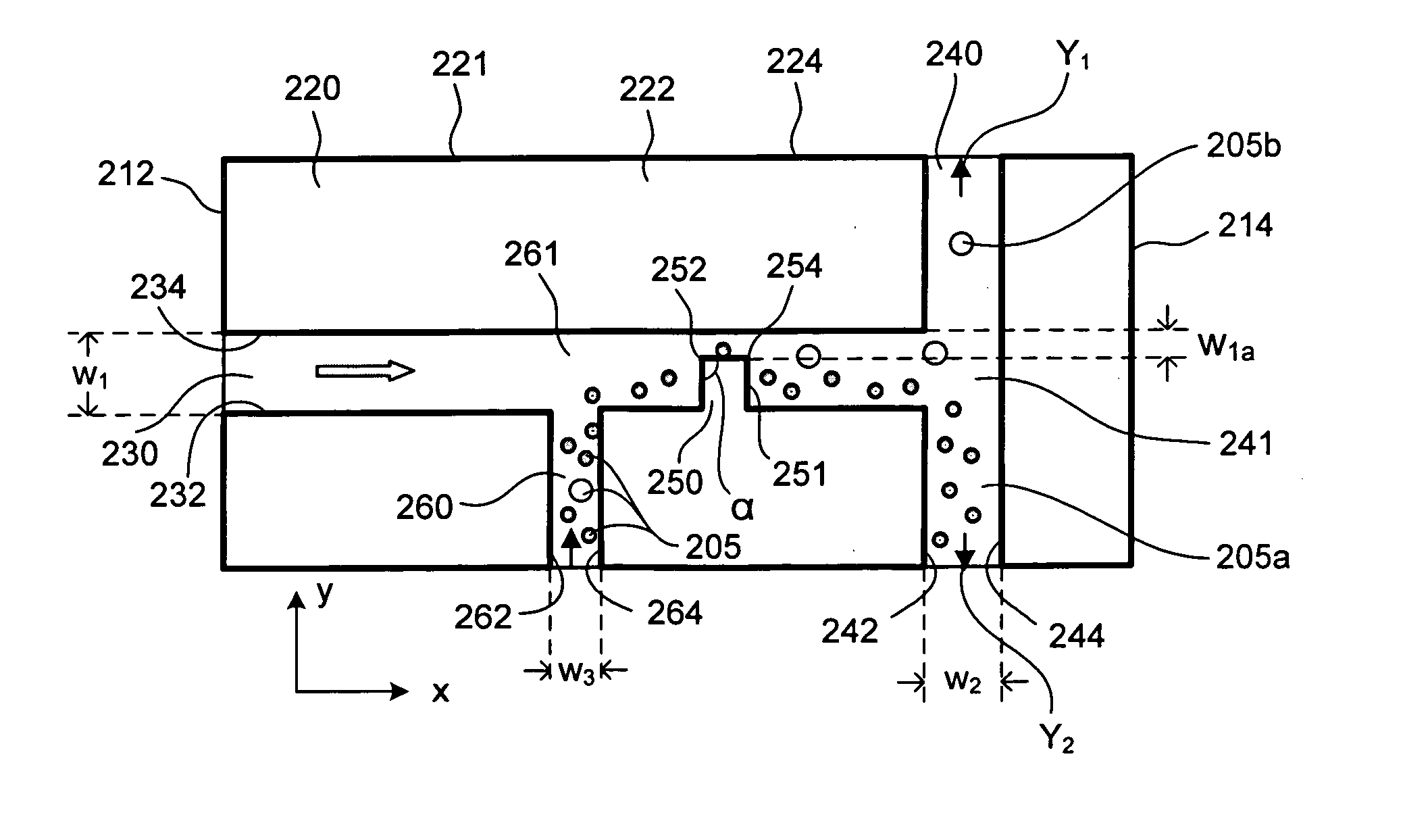
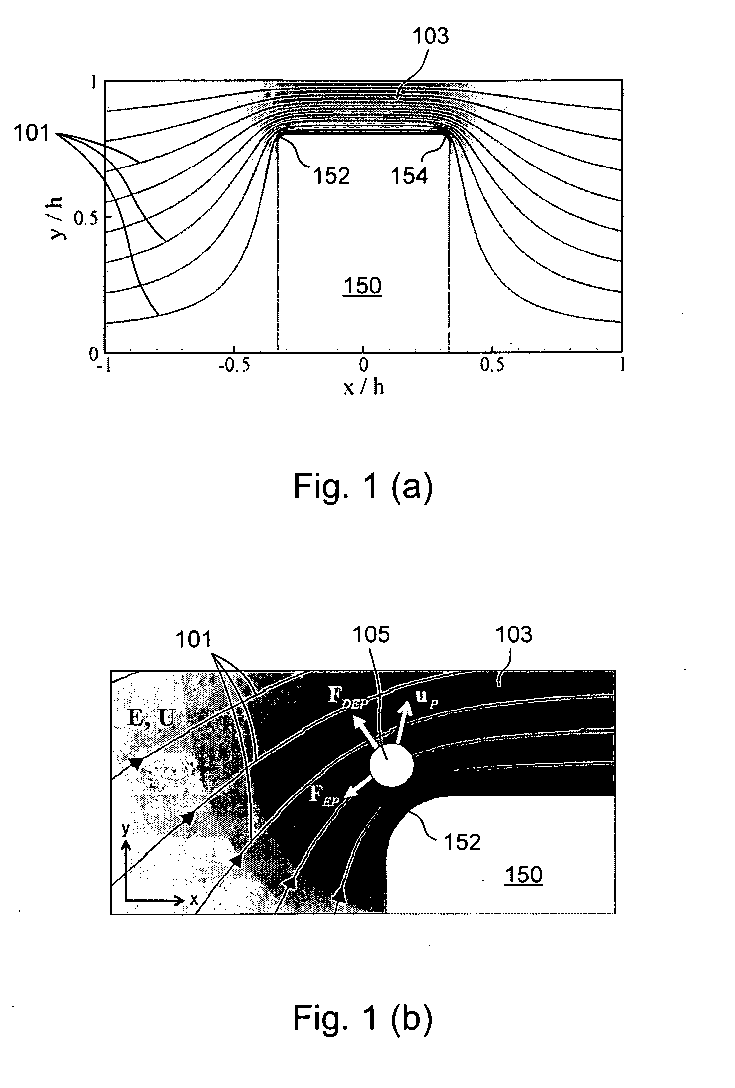
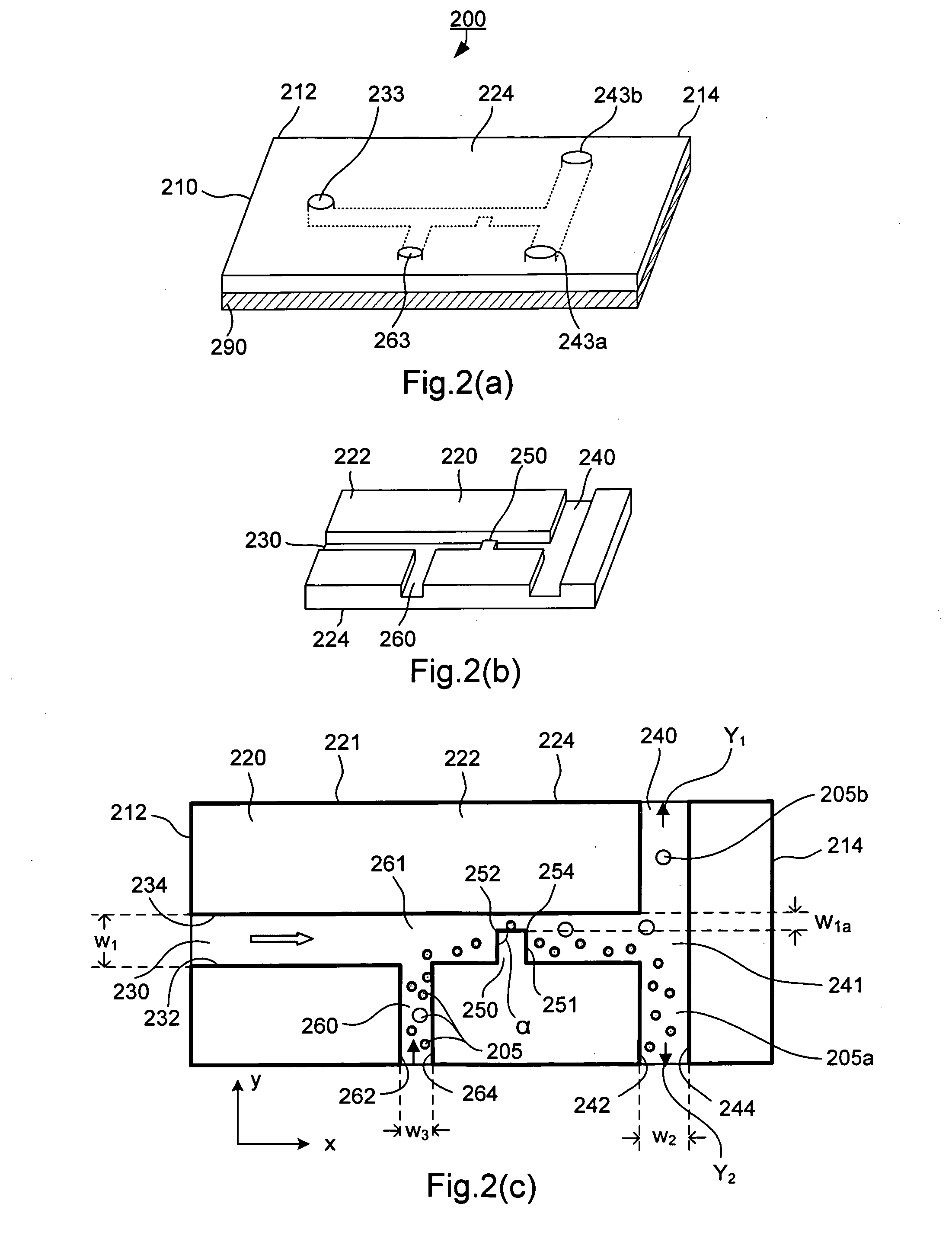
[0139]FIG. 11 shows trajectories of 6 μm and 15 μm polystyrene particles by superimposing a series of sequential microscopy images obtained from an experiment. The microchannel (made of PDMS and glass by soft lithography) in this case was 300 μm in width and 40 μm in depth (perpendicular to the paper). The narrow section of the microchannel was 60 μm in width. We found that when the mixed particles approached the narrow gap from the side of the hurdle, the DC-DEP effect produced the best separation. As set forth above, when larger particles and smaller particles move closely over the corner of the hurdle where the non-uniform electrical field gradient is the strongest, the larger particles are subject to a stronger DEP force and are pushed further away from the corner compared with smaller particles. Consequently the larger particles and smaller particles follow separate trajectories after passing the hurdle. Applying appropriate voltages to induce the downstream flows to the two se...


PUM

PropertyMeasurementUnit
angleaaaaaaaaaa
sizeaaaaaaaaaa
sizeaaaaaaaaaa

Abstract

The present invention relates to an apparatus and methods of separating particles or cells according to their sizes, wherein the size of each of the particles or cells is characterized by a corresponding diameter. In one embodiment, the method includes the steps of providing a microchannel structure having at least one channel that is defined by a first sidewall and a second, opposite sidewall and has an insulating protrusion formed on one of the first sidewall and the second, opposite sidewall, introducing a plurality of particles or cells in a liquid medium into the at least one channel, and generating a non-uniform electrical field in the at least one channel such that when the plurality of particles or cells passes by the insulating protrusion, the plurality of particles or cells each receives a dielectrophoretic force proportional to its diameters, thereby being separable according to their sizes. The method further has the step of collecting particles or cells after the separation of particles or cells.

Description

CROSS-REFERENCE TO RELATED PATENT APPLICATION[0001]This application is related to a co-pending U.S. patent application entitled “Microfluidic Flow Cytometer and Applications of Same”, by Dongqing Li with Attorney Docket No. 14506-55548, filed Sep. 19, 2006, which has the same assignee as the present application and has been concurrently filed herewith. The applicant of that application is also applicant of this application. The disclosure of the above-identified co-pending application is incorporated in its entirety herein by reference.[0002]Some references, which may include patents, patent applications and various publications, are cited and / or discussed in the description of this invention. The citation and / or discussion of such references is provided merely to clarify the description of the present invention and is not an admission that any such reference is “prior art” to the invention described herein. All references cited including those listed in the List of References and / o...

Claims


Application Information

Patent Timeline
Patent Type & Authority Applications(United States)
IPC IPC(8): C07K1/26G01N27/00
CPCB03C5/005C07K1/26B03C5/026
Inventor LI, DONGQING
Owner VANDERBILT UNIV
Why Eureka
Try Eureka