Projection optical system and image projecting apparatus

a projection optical system and projector technology, applied in the direction of projectors, color television details, instruments, etc., can solve the problems of difficult to obtain a large-format liquid crystal display device, difficult to set a projector location, and high cos

Active Publication Date: 2008-03-20
RICOH KK
View PDF4 Cites 47 Cited by
  • Summary
  • Abstract
  • Description
  • Claims
  • Application Information

AI Technical Summary

Problems solved by technology

However, it is not easy to obtain a large-format liquid crystal displaying device with no defect in the production thereof in order to increase the surface area of a light valve, itself, for projecting a large image, and if it were obtained, it would be extremely expensive.
However, when a situation of practical utilization of a projector is assumed, a location for setting a projector may be problematic.
For example, when a front-type projector for projecting an image in front in an office is utilized by a few people in a relatively small conference room, no small restriction is provided on a location for setting a projector due to, for example, the size of a projected image, a projection distance, connection with a PC, a table layout for comfortable discussion, and a problem of less usability thereof may occur.
Then, a shadow of the presenter may be reflected on the screen and a problem may occur such that an audience cannot see a portion of a projected image.
However, for example, a projection distance of at least about 1 m is required for a front-type one in order to obtain an image with a diagonal size of 50-60 inches in a conventional technique, and at such a distance, a problem often occurs such that the shadow of a presenter reflects on a screen.
Herein, even if several times of folding are made with, for example, plane mirrors in a housing, there is a limitation on miniaturization of the device, itself, and therefore, reduction of a projection distance of an optical system is desired increasingly.
A common problem to the conventional techniques described above is to use many aspheric surfaces including a free-form surface in order to maintain an imaging performance and realize a wide angle of view, and accordingly, it is necessary to keep a strict precision of the distanc...

Method used


Image

  • Projection optical system and image projecting apparatus
  • Projection optical system and image projecting apparatus
  • Projection optical system and image projecting apparatus

Examples


example 1

PRACTICAL EXAMPLE 1

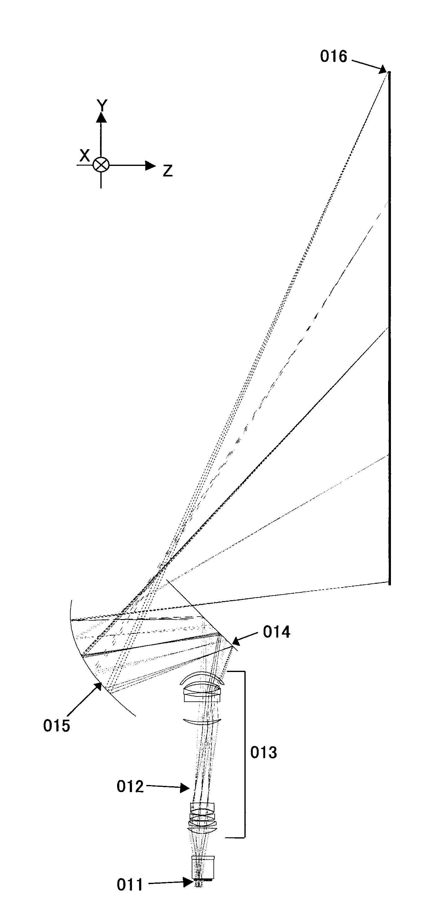
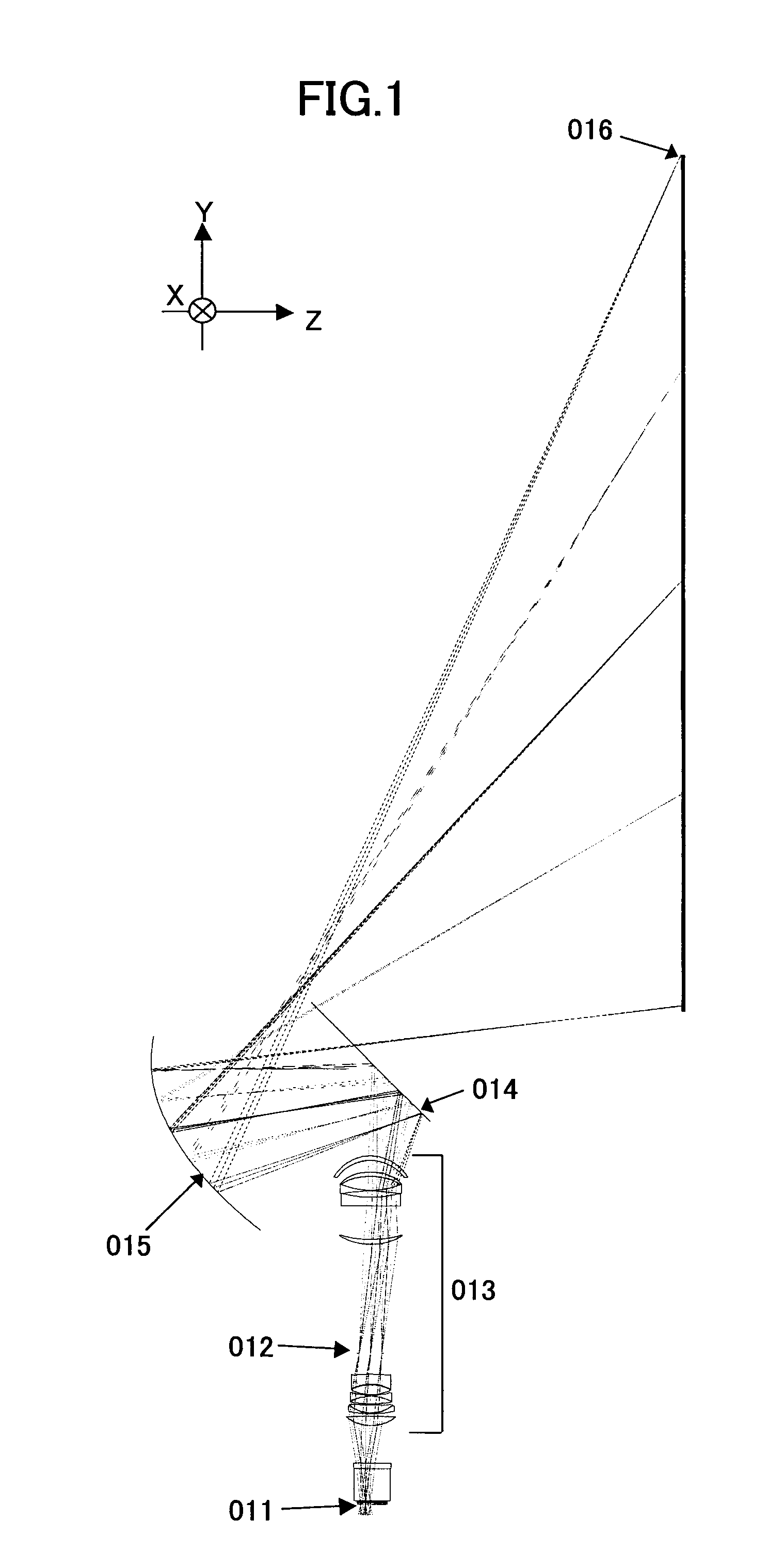
[0069]Practical example 1 of the present invention is shown in FIG. 1.

[0070]Herein, in regard to the coordinate system in the figures illustrating examples of the present invention, X is the directions of the major axis of a screen on a conjugate plane B, Y is the directions of the minor axis thereof, and Z is the directions of the normal of the screen.

[0071]A projection optical system is to project an image formed by an image forming element 011 on a conjugate plane A onto a screen 016 on a conjugate plane B, and is composed of a first optical system 013 that is a coaxial system and includes at least one refractive optical system and a second optical system 015 that includes at least one reflective surface having a positive power, wherein the first optical system 013 and the second optical system 015 are arranged from the image forming element 011, and an intermediate image between the first optical system 013 and the second optical system 015 is once formed from...

example 2

PRACTICAL EXAMPLE 2

[0093]Next, practical example 2 for the second embodiment of the present invention is described below.

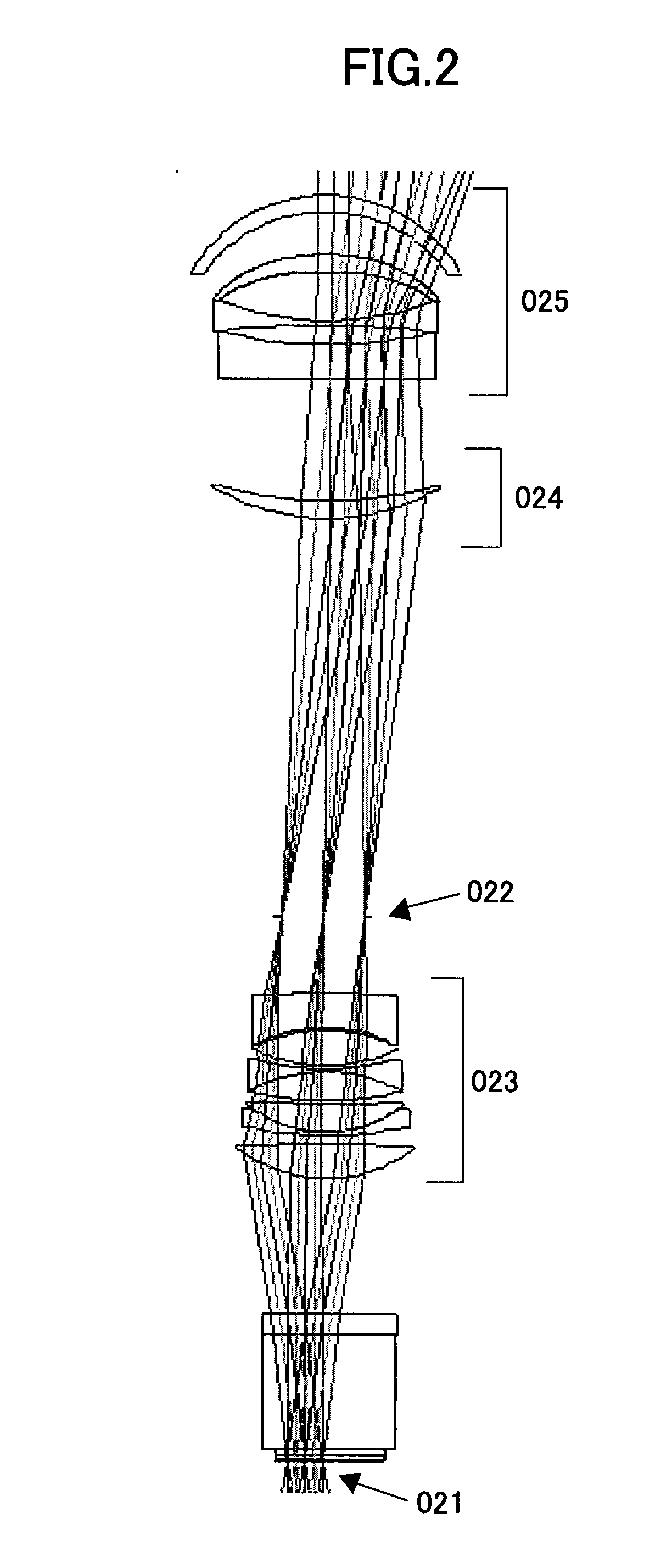
[0094]FIG. 7 shows practical example 2 and FIG. 8 shows an enlarged view of a first optical system in practical example 2.

[0095]Similarly to practical example 1 of the present invention, a projection optical system is to project an image formed by an image forming element 071 on a conjugate plane A onto a screen 076 on a conjugate plane B, and is composed of a first optical system 072 that is a coaxial system and includes at least one refractive optical system and a second optical system 074, 075 that includes at least one reflective surface having a positive power, wherein the first optical system 072 and the second optical system 074, 075 are arranged from the image forming element 071, and an intermediate image between the first optical system 072 and the second optical system 074, 075 is once formed from the image formed from on the image forming element 071. ...

example 3

PRACTICAL EXAMPLE 3

[0101]Next, practical example 3 for the fifth embodiment of the present invention is described below.

[0102]FIG. 13 shows practical example 3 and FIG. 14 shows an enlarged view of a first optical system in practical example 3.

[0103]Similarly to practical example 1 of the present invention, a projection optical system is to project an image formed by an image forming element 131 on a conjugate plane A onto a screen 136 on a conjugate plane B, and is composed of a first optical system 133 that is a coaxial system and includes at least one refractive optical system and a second optical system 135 that includes at least one reflective surface having a positive power, wherein the first optical system 133 and the second optical system 135 are arranged from the image forming element 131, and an intermediate image between the first optical system 133 and the second optical system 135 is once formed from the image formed from on the image forming element 131. It is an optic...


PUM


Abstract

A projection optical system including a first optical system configured to form a second image conjugate to a first image and a second optical system configured to include a reflective optical element which reflects light from the second image and to project a third image conjugate to the second image onto a projection surface is provided, wherein the first optical system includes a stop and at least one optical element with a positive refractive power and at least one optical element with a negative refractive power which are provided between the stop and the second image, and an optical element with a strongest positive refractive power in the at least one optical element with a positive refractive power is provided between the stop and an optical element with a strongest negative refractive power in the at least one optical element with a negative refractive power.

Description

BACKGROUND OF THE INVENTION[0001]1. Field of the Invention[0002]The present invention relates to a projection optical system and an image projecting apparatus.[0003]2. Description of the Related Art[0004]In recent years, an enlarging projection system has attracted attention which uses a displaying device (referred to as a light valve, below) in which a transmission-type or reflection-type dot matrix liquid crystal and a DMD (Digital Micro-mirror Device) is used and which enlarges and projects an image displayed on the light valve onto a screen so as to exhibit it as a large image.[0005]However, it is not easy to obtain a large-format liquid crystal displaying device with no defect in the production thereof in order to increase the surface area of a light valve, itself, for projecting a large image, and if it were obtained, it would be extremely expensive.[0006]In such a situation, when a light valve such as a transmission-type (or reflection-type) liquid crystal and a DMD is used a...

Claims


Application Information

Patent Timeline
IPC IPC(8): G03B21/28
CPCG02B13/16G02B17/08G02B17/0812H04N9/3197G03B21/14G03B21/28H04N9/3102G02B17/0852G03B21/147
Inventor ABE, ISSEIFUJITA, KAZUHIROTAKAURA, ATSUSHI
Owner RICOH KK
Why Eureka
Try Eureka