
Optical pickup

Inactive Publication Date: 2008-03-20
FUNAI ELECTRIC CO LTD
View PDF7 Cites 11 Cited by
  • Summary
  • Abstract
  • Description
  • Claims
  • Application Information

AI Technical Summary

Benefits of technology

[0014] In view of the above problem, it is an object of the present invention to enable to obtain stable signals by suppressing displacement of optical intensity distribution at a light receiving section in a multiple wavelength-adaptive optical pickup.
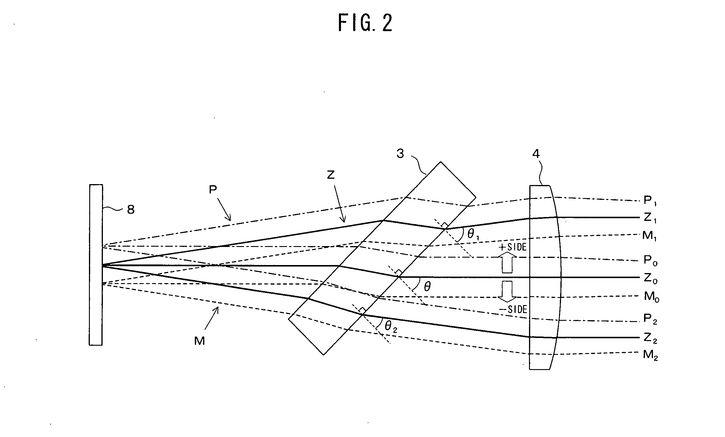
[0016] In the present invention, a wavelength at which the variation in transmittance (reflectance) of the beam splitter is maximized is set as a standard. When the variation occurs on the side where the incident angle is larger than θ (plus side) in this wavelength, the diffraction one-dimensional beam on the side where the incident angle is smaller than θ (minus side) is used for detecting the signals for servo control, and when the variation occurs on the side where the incident angle is smaller than θ (minus side), the diffraction one-dimensional beam on the side where the incident angle is larger than θ (plus side) is used for detecting the signals for servo control. Thus, by taking aim at a wavelength in which the variation in transmittance (reflectance) is maximized and using the diffraction one-dimensional beam on the side where the variation is small, it is possible to minimize the effects by the incident angle dependency of the transmittance (reflectance) as a whole and to decrease the displacement of the optical intensity distribution at the light receiving section. Consequently, when tracking error signals are detected according to the diffraction one-dimensional beam, an offset due to the displacement of the optical intensity distribution is reduced, and accuracy of tracking control is improved.
[0018] In accordance with the present invention, it is possible to obtain stable signals with less offset by suppressing displacement of optical intensity distribution at a light receiving section resulting from the incident angle dependency of the transmittance of the beam splitter in a multiple wavelength-adaptive optical pickup.

Problems solved by technology

Therefore, when tracking error signals are detected based on the diffraction one-dimensional beam, there is a problem that, if shift of the optical intensity distribution occurs due to the variation in transmittance, an offset is generated in the tracking error signal and accuracy of tracking control is deteriorated.

Method used


Image

  • Optical pickup
  • Optical pickup
  • Optical pickup

Examples


Embodiment Construction

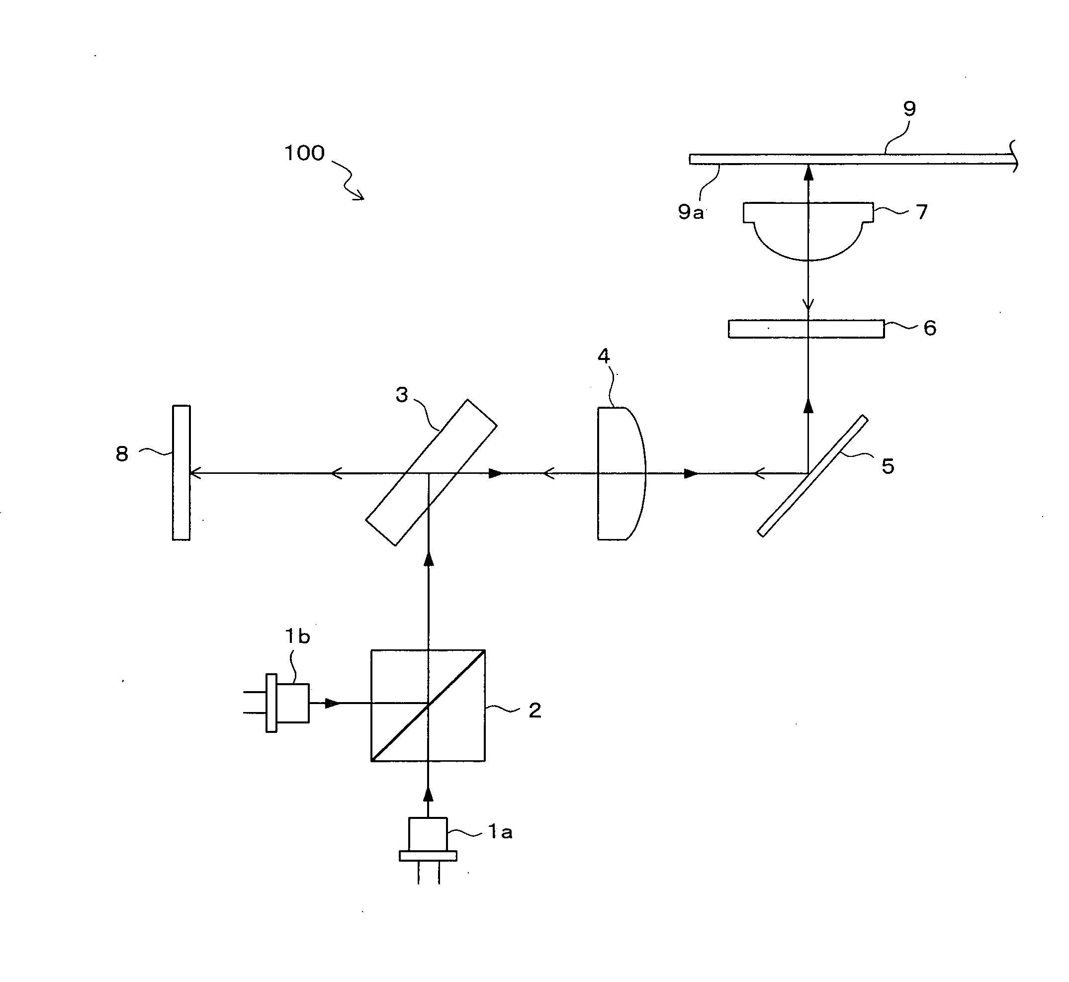
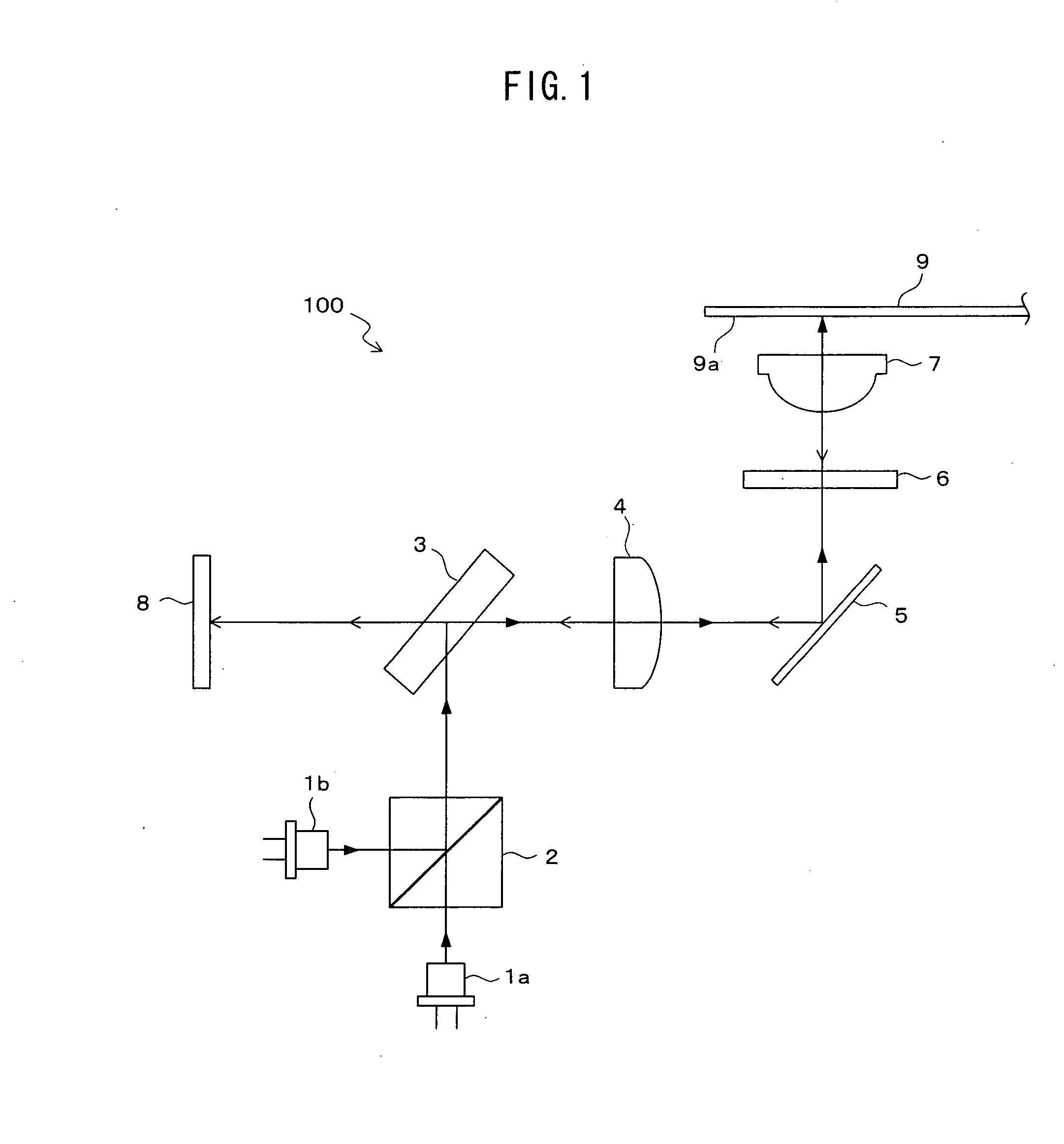
[0027] Hereinafter, an embodiment of the present invention will be described with reference to the drawings. FIG. 1 is a view showing an optical constitution of an optical pickup 100 according to the present invention. A first light emitting device 1a for a CD and a DVD includes two semiconductor lasers for projecting an infrared laser beam having a wavelength of 780 nm and a red laser beam having a wavelength of 650 nm, respectively. A second light emitting device 1b for a BD and a HD-DVD includes a semiconductor laser for projecting a blue laser beam having a wavelength of 410 nm. A prism 2 transmits the laser beam from the light emitting device 1a and allows it to go straight, and reflects the laser beam from the light emitting device 1b to turn an optical path thereof by an angle of 90°. A half mirror 3 forms a beam splitter, and reflects the beam passed through the prism 2 at an angle of 90° toward a collimating lens 4, and transmits the beam from the collimating lens 4 directl...


PUM


Abstract

A multiple wavelength-adaptive optical pickup according to the present invention enables to obtain stable signals by suppressing displacement of optical intensity distribution at a light receiving section. When an incident angle of a central beam of a zero-dimensional beam of a beam reflected at an optical disc into a half mirror is taken as θ, if variation in transmittance of the mirror become a maximum with respect to change in the incident angle from θ to a plus side in any one of the wavelengths corresponding to the respective optical discs, a −1 dimensional beam generated on the minus side with respect to the zero-dimensional beam is received by the light receiving section, and if the variation in the transmittance of the mirror become the maximum with respect to change in the incident angle from θ to the minus side, a +1 dimensional beam generated on the plus side with respect to the zero-dimensional beam is received by the light receiving section. These received one-dimensional beams are used for detection of signals for servo control.

Description

BACKGROUND OF THE INVENTION [0001] 1. Field of the Invention [0002] The present invention relates to an optical pickup used for reading information on an optical disc in a DVD recorder, a personal computer or the like. [0003] 2. Description of the Related Art [0004] As image or audio recording media, optical discs such as a DVD (digital versatile disc) and a CD (compact disc) have come into widespread use today. Further, recently, new optical discs such as a Blu-ray Disc (trademark) and a HD-DVD (high definition digital versatile disc) capable of recording larger-capacity data have appeared. [0005] In such a optical disc, reading information and servo control are performed by projecting laser beam with a predetermined wavelength on an information recording surface of the disc and receiving reflected beam of the laser beam. The wavelength of the laser beam varies in accordance with the species of optical discs. For example, infrared laser beam with a wavelength of 780 nm is used for ...

Claims


Application Information

Patent Timeline
IPC IPC(8): G11B7/00
CPCG11B7/0901G11B7/094G11B2007/0006G11B7/1365G11B7/1395G11B7/131
Inventor IKEDA, ATSUSHI
Owner FUNAI ELECTRIC CO LTD
Learn More