Method for Manufacturing Hot Cathode Fluorescent Lamp

a technology of fluorescent lamps and manufacturing methods, which is applied in cold cathode manufacturing, electric discharge tube/lamp manufacturing, and electric system manufacturing. it can solve the problems of small flare stems, possible contact with each other or other problems, and difficulty in using larger flare stems to ensure dimensional accuracy. it achieves stable initial luminous intensity, and improves product life characteristics

Inactive Publication Date: 2008-03-20
STANLEY ELECTRIC CO LTD
View PDF3 Cites 2 Cited by
  • Summary
  • Abstract
  • Description
  • Claims
  • Application Information

AI Technical Summary

Benefits of technology

[0015] The presently disclosed subject matter has been developed in view of the foregoing features, problems, and characteristics associated with conventional technologies. A method for manufacturing a hot cathode fluorescent lamp is disclosed which attempts to ensure the stable initial luminous intensity and provide improved product life characteristics even if the hot cathode fluorescent lamp employs a glass tube with a smaller outer diameter. The presently disclosed subject matter also relates to a method for manufacturing a hot cathode fluorescent lamp with good productivity and with good reproduction stability.
[0019] Accordingly, it is not necessary for the clamp section to have an air discharge function. This can eliminate any complex chucking function for supplying a current.
[0021] On the contrary, in accordance with an aspect of the disclosed method for manufacturing a hot cathode fluorescent lamp, the glass tube and the exhaust pipe are integrally welded with the lead wires being sandwiched therebetween. Accordingly, the bead stem sealing the lead wires can be fixed in position within the glass tube by means of the sandwiched lead wires. Consequently, the filament supported by and connected to the lead wires which are sealed in the bead stem can be kept at a predetermined position within the glass tube with high positional accuracy.
[0022] This can prevent any contact of the filament coil with the inner wall of glass tube, thereby ensuring or at least making more likely the stable activation of the emitter as well as stable initial luminous intensity. Further to this, the product life characteristics of the hot cathode fluorescent lamp itself as well as the reproducibility of production can be improved.
[0023] In accordance with an aspect of the presently disclosed subject matter, the inner diameter of the exhaust pipe may be equal to or greater than the inner diameter of the glass tube. By doing so, it is possible to increase an exhaust rate from the vacuum system, thereby improving the production efficiency.

Problems solved by technology

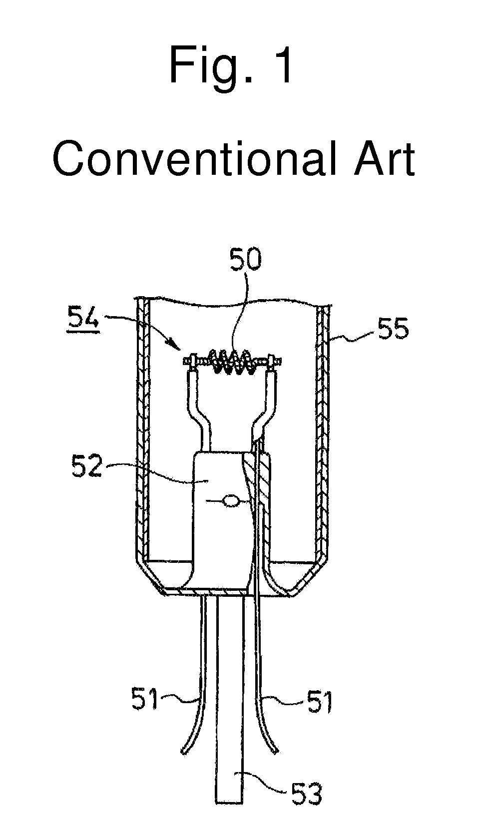
Since the flare stem 52 must be formed by flame processing, it is difficult to use a larger-sized flare stem to ensure the dimensional accuracy.
Therefore, the miniaturization of such a flare stem is limited.
Accordingly, if the lead wires extend over a long distance, the wires may sag and / or bend undesirably, resulting in possible contact with each other or other problems.
In this case, only with the bead stem, it is difficult to secure a certain gap between the filament coil and the inner wall of the glass bulb with high accuracy.
If the filament coil comes into contact with the inner wall of the glass bulb, the heat generated at the filament coil may transfer to the glass bulb, resulting in a deterioration of the stable activation of the emitter.
This may lead to unstable luminous intensity at the time of turning on.
Furthermore, this may undesirably affect the product life characteristics of the hot cathode fluorescent lamp itself.
In some cases, the filament supported by and connected to the lead wires which are sealed in the bead stem may tilt to deteriorate the positional accuracy of the filament, resulting in possible contact with the inner wall of the glass tube.

Method used


Image

  • Method for Manufacturing Hot Cathode Fluorescent Lamp
  • Method for Manufacturing Hot Cathode Fluorescent Lamp
  • Method for Manufacturing Hot Cathode Fluorescent Lamp

Examples


Embodiment Construction

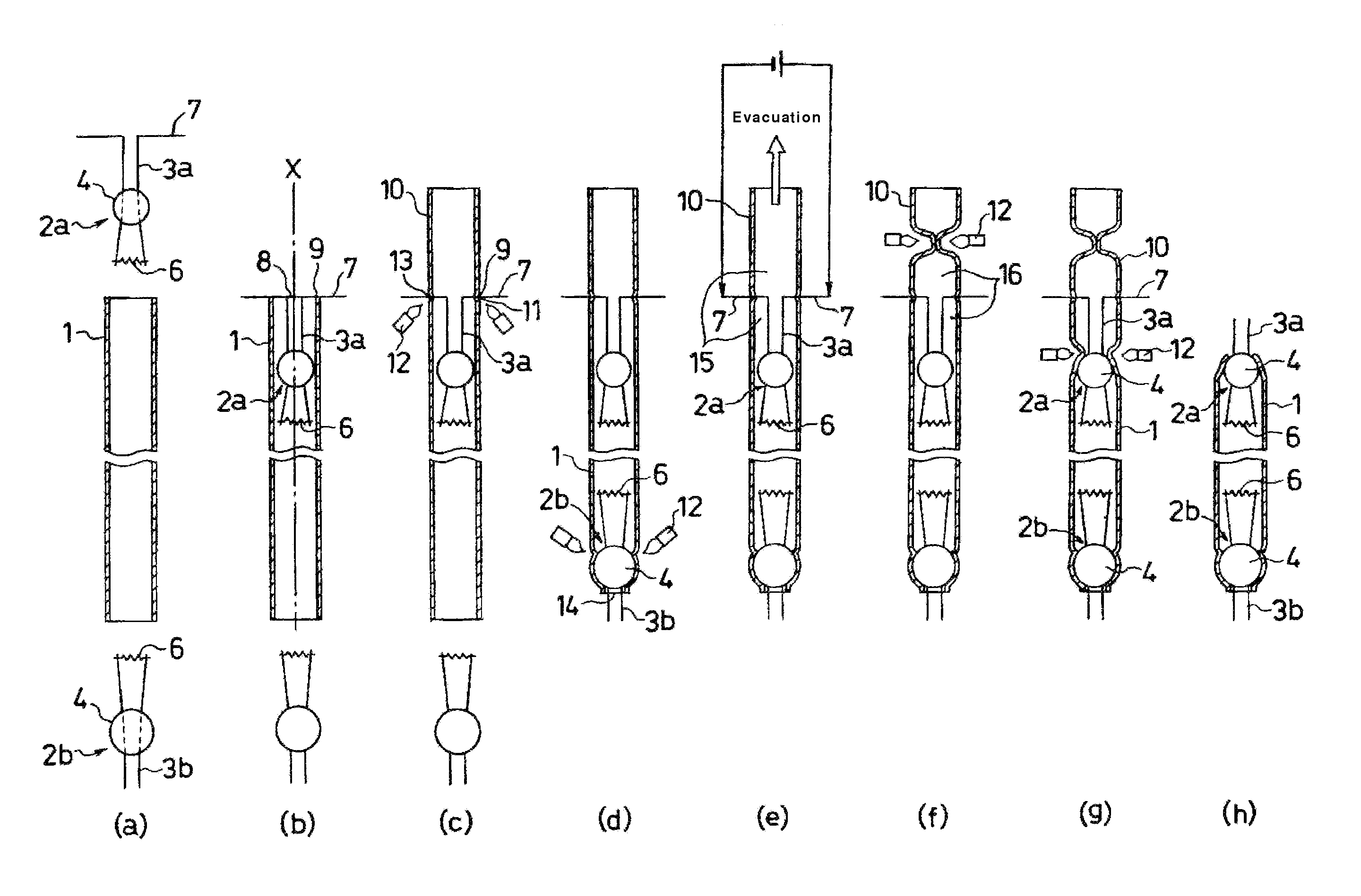
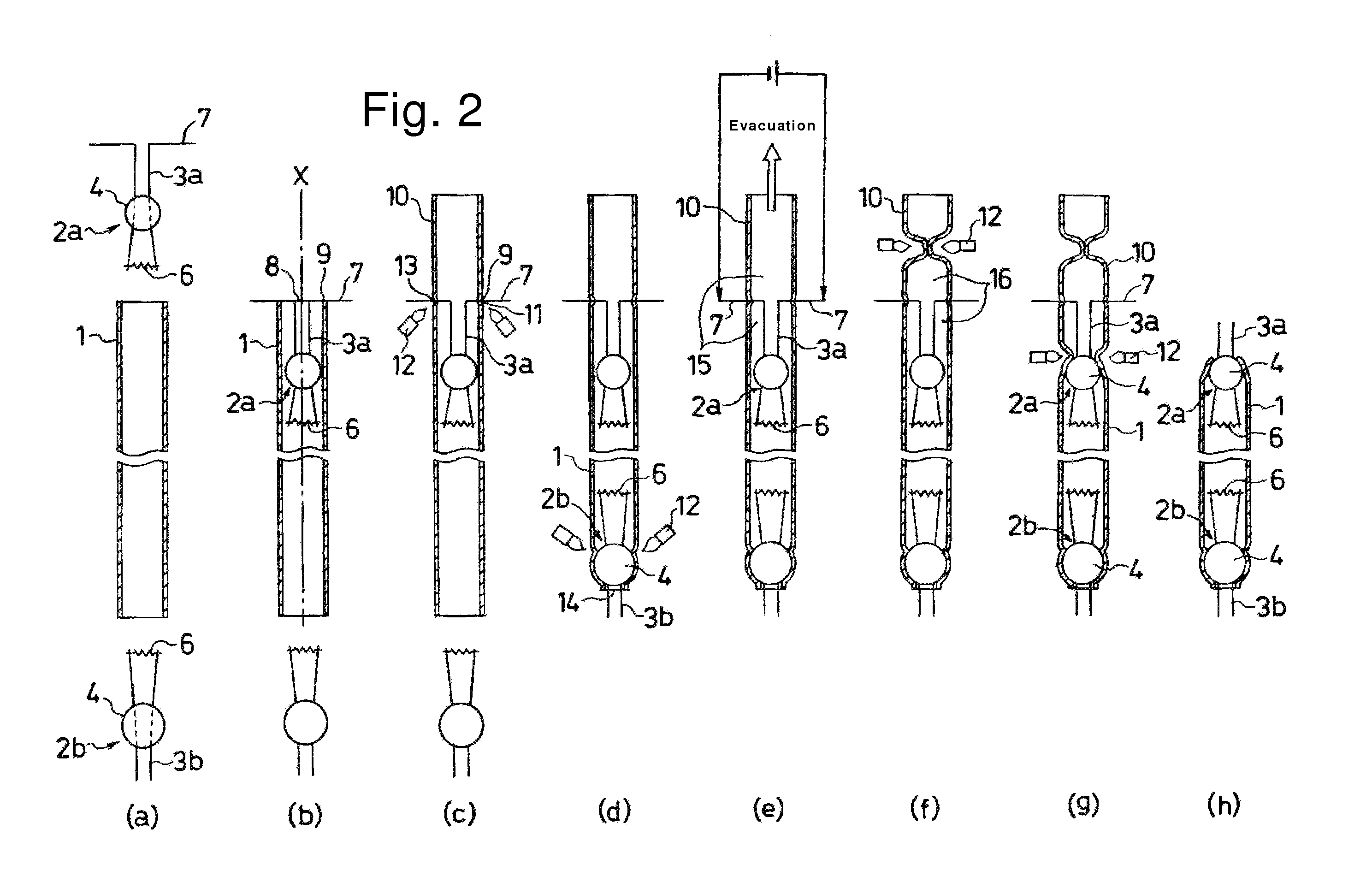
[0032] A description will now be given of exemplary embodiments in accordance with the presently disclosed subject matter in detail with reference to FIGS. 2 to 5. In the description, the same reference numbers refer to identical or similar sections. The exemplary embodiments described below are specific examples of the presently disclosed subject matter, so the exemplary embodiments have certain technical features and characteristics. The scope of the presently disclosed subject matter is not limited to these exemplary embodiments or their specifically disclosed features and characteristics.

[0033] FIGS. 2(a)-(h) show a method for manufacturing a hot cathode fluorescent lamp in accordance with the presently disclosed subject matter. Hereinafter, the manufacturing processes will be described in detail.

[0034] In the process shown in FIG. 2(a), a glass tube 1 and two mounts 2a and 2b are prepared. Each mount 2a (2b) includes a glass bead 4 and a pair of metal lead wires 3a (3b) seale...


PUM


Abstract

A method for manufacturing a hot cathode fluorescent lamp can ensure or facilitate stable initial luminous intensity and provide improved product life characteristics even when the hot cathode fluorescent lamp employs a glass tube with an outer diameter of less than 7 mmφ. One end of a glass tube can be sealed with a glass bead of a mount structure. The other opening end of the glass tube can be welded with an opening end of an exhaust pipe with bent portions of lead wires being sandwiched between the opening ends of the glass tube and the exhaust pipe. After evacuating a vacuum system that is constituted by the inner spaces of the glass tube and the exhausted pipe communicating with each other, the bent portions of the lead wires which extrude outside the vacuum system can be clamp-connected to power source lines extending from an external power source. The emitter of the filaments can be activated by the generated heat of the filament. After supplying mercury and a rare gas into the glass tube, the glass bead can be sealed, and unnecessary portions of the glass tube, the exhaust pipe, and the lead wires can be removed to complete the hot cathode fluorescent lamp, in accordance with one aspect of the disclosed subject matter.

Description

[0001] This application claims the priority benefit under 35 U.S.C. §119 of Japanese Patent Application No. 2006-249597 filed on Sep. 14, 2006, which is hereby incorporated in its entirety by reference. BACKGROUND [0002] 1. Technical Field [0003] The presently disclosed subject matter relates to a method for manufacturing a hot cathode fluorescent lamp. [0004] 2. Description of the Related Art [0005] Hot cathode fluorescent lamps have a filament coated with an emissive material (being a so-called “emitter”) in the form of carbonate. If such a filament is supplied with a current while under vacuum, heat energy is generated at the filament, thereby changing the emitter that is in the form of carbonate into the corresponding metal oxide (being activated) to exhibit an electron emission characteristic. [0006] One conventional exemplary configuration of such a hot cathode fluorescent lamp is shown in FIG. 1. The hot cathode fluorescent lamp has mounts 54 and a glass bulb 55. The mount 54...

Claims


Application Information

Patent Timeline
Patent Type & Authority Applications(United States)
IPC IPC(8): H01J9/08
CPCH01J9/323H01J61/70H01J9/40H01J9/38
Inventor MATSUBARA, NAOYUKIKANECHIKA, MASAYUKITAKAO, YOSHIFUMIMIYAMOTO, KAZUHIRONAGAHARA, TOSHIYUKIMATSUDA, JUNJI
Owner STANLEY ELECTRIC CO LTD
Why Eureka
Try Eureka