System And Method For Assisted Partitioning Of Body Conduits

a technology of body conduits and assisted partitioning, which is applied in the direction of prosthesis, blood vessels, therapy, etc., can solve the problems of tens of millions of patients worldwide, cardiovascular morbidity and mortality, and congestive heart failur

a technology of body conduits and assisted partitioning, which is applied in the direction of prosthesis, blood vessels, therapy, etc., can solve the problems of tens of millions of patients worldwide, cardiovascular morbidity and mortality, and congestive heart failur

US20080071135A1Inactive Publication Date: 2008-03-20SHAKNOVICH ALEXANDER

Image

  • System And Method For Assisted Partitioning Of Body Conduits
  • System And Method For Assisted Partitioning Of Body Conduits
  • System And Method For Assisted Partitioning Of Body Conduits

Examples


Embodiment Construction

[0045] This invention will be further understood in view of the following detailed description of exemplary embodiments.

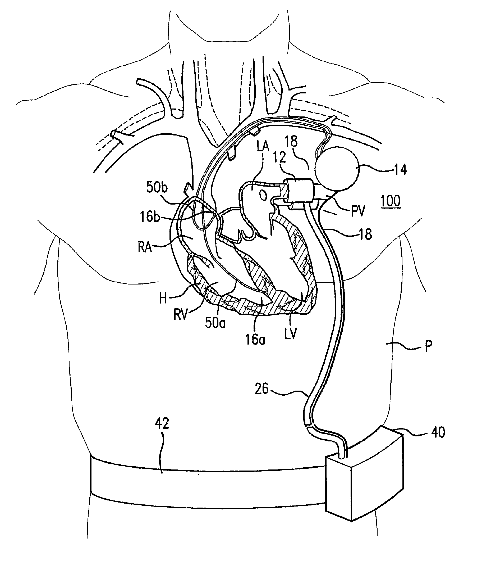
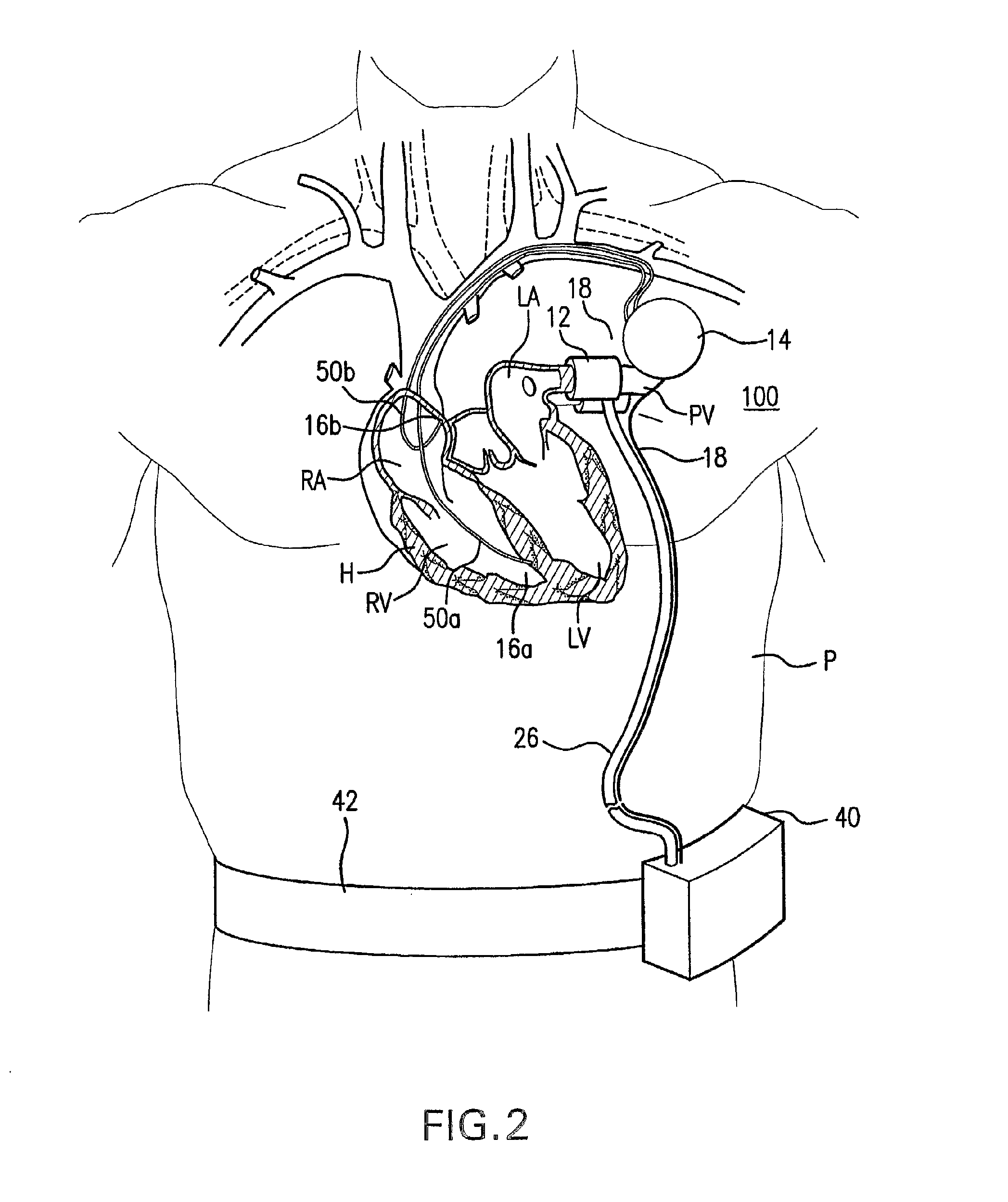
[0046] A system in accordance with an exemplary embodiment of the invention provides effective partitioning between body conduits is illustrated in FIG. 2, and generally designated system 100. This system implanted in patient P finds particularly useful application in providing effective partitioning between the left atrium LA of the patient's heart H and one of more of the four pulmonary veins PV for the purpose of lowering mean pulmonary venous pressure, and therefore treatment of conditions such as, e.g., congestive heart failure. Alternatively, the system is useful for treating physiological parameters, e.g., elevated pulmonary venous pressures, independently from physical conditions. Additional methods for partitioning the left atrium from the pulmonary veins is disclosed in U.S. Pat. No. 6,572,652, which is hereby incorporated by reference in its entirety he...


PUM


Abstract

A treatment strategy for treatment of elevated pressure in a body conduit, such as a pulmonary vein, with a prosthetic partitioning device for placement in and / or about pulmonary veins is described, as well as delivery systems, and strategies for use thereof. A control device is configured to transmit signals to the prosthetic device to effectuate the repetitive transition between a first, less restricted flow configuration and a second, restricted flow configuration are described. A sensor device may be provided for monitoring physiological parameters of the patient, and can provide signals to the control device for effectuating the transition between the first and second configuration.

Description

CROSS-REFERENCE TO RELATED APPLICATIONS [0001] This application claims the benefit of U.S. Provisional Patent Application Ser. No. 60 / 618,010, filed Oct. 12, 2004, entitled “System and Method For Assisted Partitioning of Body Conduits,” which is hereby incorporated by reference in its entirety herein.BACKGROUND [0002] 1. Field of the Invention [0003] The present invention relates generally to the field of systems and methods for partitioning body conduits with a class of prosthetic partitioning devices, specifically with prosthetic devices for placement in and / or about pulmonary vein(s) for the purpose of treating congestive heart failure, to procedures for installing same. [0004] 2. Background of the Invention [0005] Congestive heart failure is a complex syndrome of various etiologies associated, in some patients, with abnormally high pulmonary venous pressures at rest and / or in conjunction with physical, emotional or metabolic stress. Congestive heart failure is a major cause of c...

Claims


Application Information

Patent Timeline
20 Mar 2008
Publication
US20080071135A1
IPC
A61M1/12; A61F2/06
CPC
A61B5/026; A61B5/042; A61B5/0452; A61B17/12031; A61B2017/1205; A61B17/12136; A61B17/135; A61B2017/00557
Inventors
SHAKNOVICH, ALEXANDER