Device for maintaining wing balance on a multi-section header

a multi-section header and wing balance technology, which is applied in the direction of mowers, harrows, etc., can solve the problems of not being able to optimize the co-operation between the cutter bar and the reel, the design requires a significantly reduced cutting speed, and the cutter bar is no longer able to maintain a close tolerance between the bats or fingers and the cutter bar, so as to achieve the flexibility of the cutter bar and simple construction

Active Publication Date: 2008-03-27
MACDON INDS
View PDF13 Cites 118 Cited by
  • Summary
  • Abstract
  • Description
  • Claims
  • Application Information

AI Technical Summary

Benefits of technology

[0139]Preferably the pivotal movement between the second frame portion and the first frame portion is less than a total of 6 degrees and more preferably less than 4 degrees, which angles are sufficient to provide the flexibility of the cutter bar which is required without p

Problems solved by technology

This type of header however has the disadvantage that the flexing or floating of the cutter bar relative to the main support tube causes movement of the cutter bar relative to the bats or fingers of the reel so that it is no longer possible to maintain a close tolerance between the bats or fingers and the cutter bar.
This floating action of a cutter bar however occurs relative to the main structural tube and therefore relative to the reel so that the cutter bar to reel co-operation cannot be optimized.
One disadvantage of the conventional flexible cutter bar is that it may in some designs require a significantly reduced cutting speed since the reciprocation of the conventional sickle knife must be reduced in velocity to accommodate the curvature of the cutter blade which can occur when the whole of the cutter blade is flexible.
A further disadvantage of a flexible cutter bar of this type is that it is necessary to set the reel at a height which accommodates the upward movement of the cutter bar which can occur.
This increased distance between the fingers of the reel and the cutter bar can cause irregular or improper feed of the crop material over the cutter bar particularly in light crop conditions so that an ac

Method used


Image

  • Device for maintaining wing balance on a multi-section header
  • Device for maintaining wing balance on a multi-section header
  • Device for maintaining wing balance on a multi-section header

Examples


Embodiment Construction

[0153]Reference is made to U.S. Pat. No. 6,865,871 (Patterson) issued Mar. 15, 2005 which disclose details of an adapter for mounting a header on a combine harvester, the disclosure of which is incorporated herein by reference.

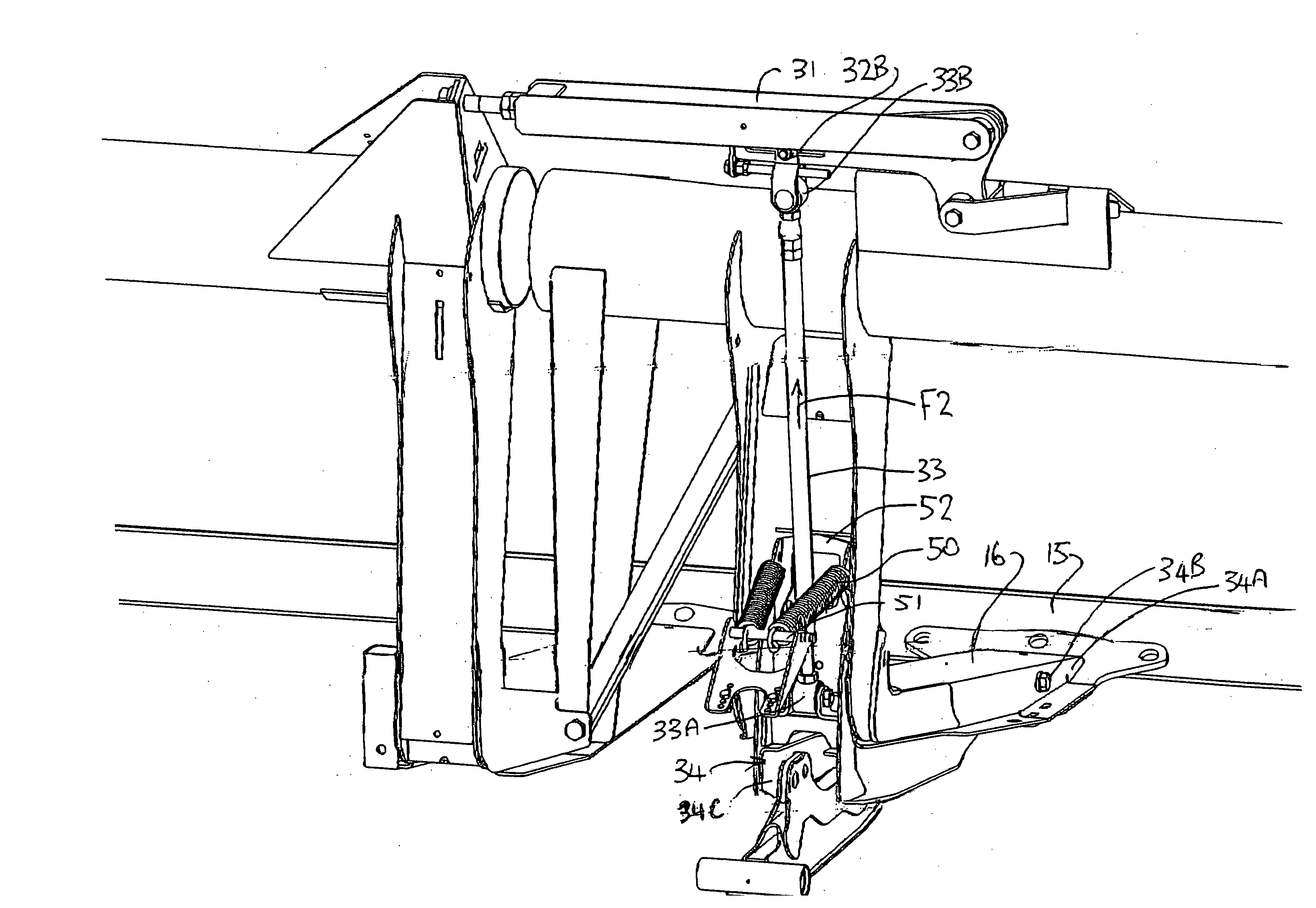
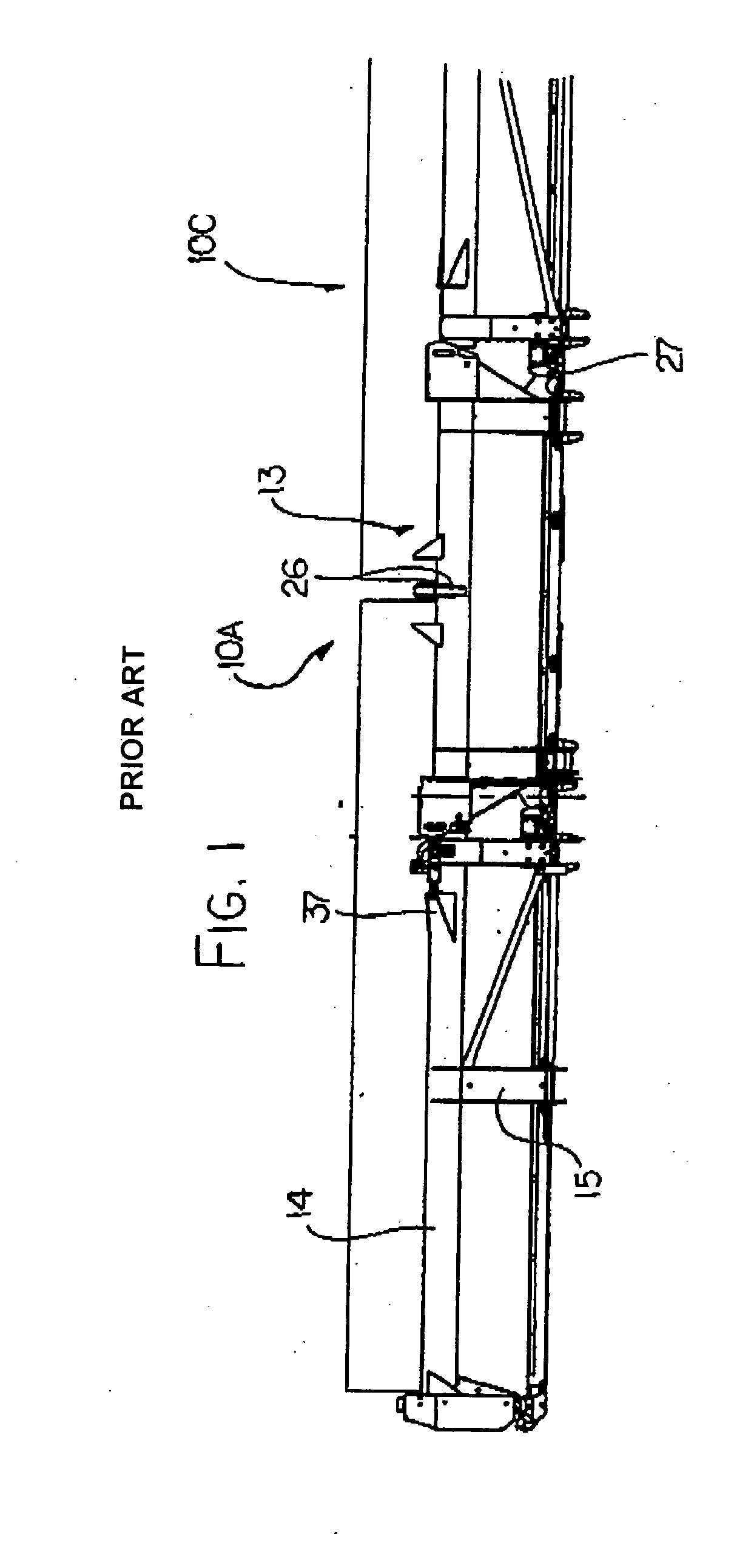
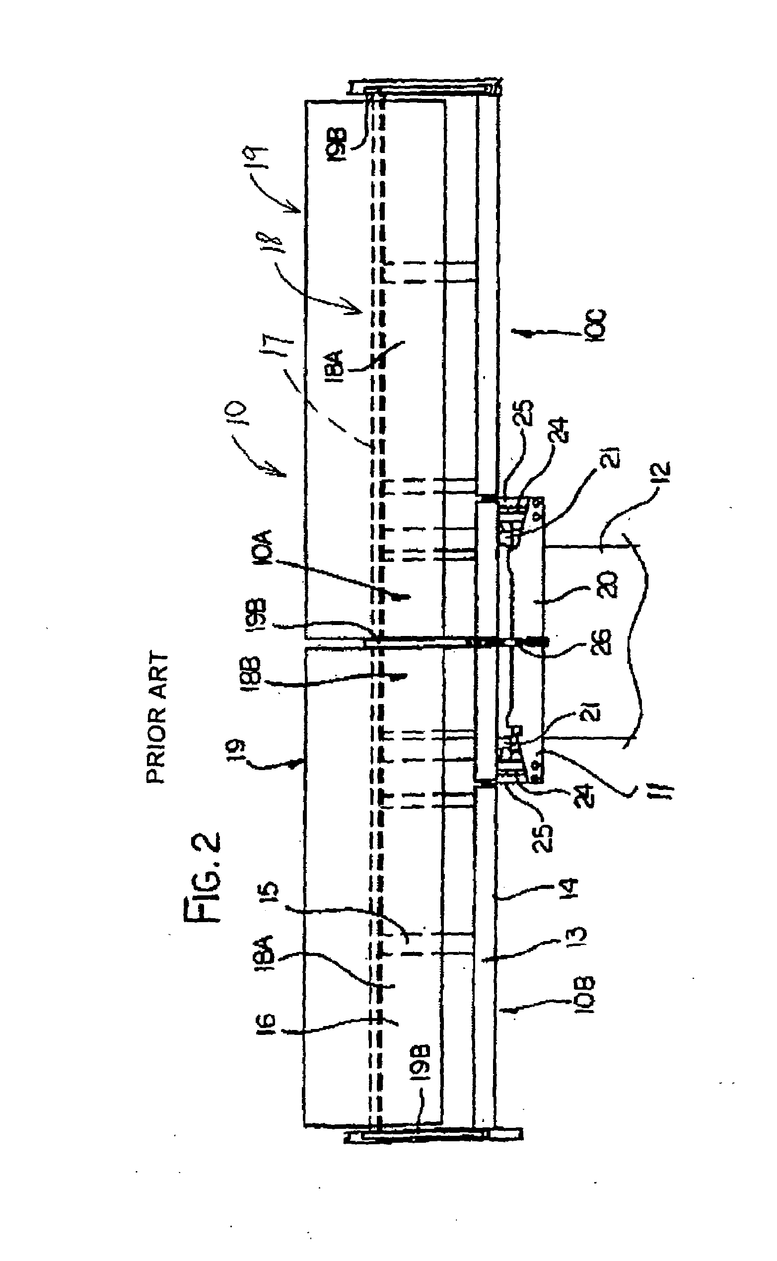
[0154]Reference is also made to U.S. Pat. No. 6,675,568 (Patterson) issued Jan. 13, 2004 which disclose details of a flexible header of the general type with which the present invention is concerned, the disclosure of which is incorporated herein by reference. FIGS. 1 and 2 and part of the following description are taken from that Patent for the convenience of the reader. Further details not included herein can be obtained by reference to that patent.

[0155]FIGS. 1 and 2 show in rear elevational view and in plan view respectively a header 10 carried on an adapter 11 attached to the feeder house 12 of a combine harvester. In FIG. 1 the adapter is omitted for convenience of illustration.

[0156]The header 10 includes a frame 13 defined by a main rear beam 14 and a ...


PUM


Abstract

A crop harvesting header includes a center portion mounted on two spring arms and two separate wings pivotally connected to the center portion. The wings are connected to the center portion by interconnecting linkages which transfer weight from the wings to the spring arms each including a balance beam arranged to balance the lifting force from the spring arm with the downward forces from the center portion and wing such that the downward force on a skid plate of each portion on the ground varies automatically as the total downward force is varied. The balance beams apply force to the linkages by a compression member to reduce forces. The movement caused by floating of the header and the change of angle of the header are compensated at the balance beam to ensure that the force to the wings is reduced as the requirement caused by changes in geometry reduces.

Description

[0001]This invention relates to header of a crop cutting apparatus such as a swather or a combine harvester which includes multiple sections defining a center section and two wing sections where the sections are balanced to maintain a constant ground force across the width as the total ground force changes.BACKGROUND OF THE INVENTION[0002]Headers for a crop harvesting machine generally comprises a main longitudinal support member in the form of an elongate tube which extends across substantially the full width of the header frame and defines a main structural member for the header frame. The tube carries a plurality of forwardly and downwardly extending support beams which include a first portion extending downwardly and a second portion attached to a lower end of the first portion and extending forwardly therefrom toward a forward end of the support beams. The cutter bar is attached to the forward end of the support beams and is thus held thereby in a position generally parallel to...

Claims


Application Information

Patent Timeline
IPC IPC(8): A01D67/00
CPCA01D41/14
Inventor TALBOT, FRANCOIS R.
Owner MACDON INDS
Why Eureka
Try Eureka