
Cold collapse method and apparatus

Inactive Publication Date: 2008-03-27
ABBOTT CARDIOVASCULAR
View PDF0 Cites 30 Cited by
  • Summary
  • Abstract
  • Description
  • Claims
  • Application Information

AI Technical Summary

Benefits of technology

[0009]The act of collapsing an SE-DES and pushing it into a catheter sheath provides several challenges. Because the stent is self-expanding, it will produce a radial force outward on any device or sheath that constrains it. The stent must be pushed from the collapsing mechanism into the catheter sheath forcefully because of the friction produced by the outward radial force, thus creating unwanted stress on the drug coating. The friction and stress on this coating has the potential to cause surface scratches or detachment of the coating. The radial force may be eliminated by cooling the stent until the stent alloy has fully transformed to the martensitic state (Mt), but an unwanted side effect is that the drug coating becomes brittle at this low temperature and can crack when the stent is collapsed.

Problems solved by technology

The stent must be pushed from the collapsing mechanism into the catheter sheath forcefully because of the friction produced by the outward radial force, thus creating unwanted stress on the drug coating.
The friction and stress on this coating has the potential to cause surface scratches or detachment of the coating.
The radial force may be eliminated by cooling the stent until the stent alloy has fully transformed to the martensitic state (Mt), but an unwanted side effect is that the drug coating becomes brittle at this low temperature and can crack when the stent is collapsed.

Method used


Image

  • Cold collapse method and apparatus
  • Cold collapse method and apparatus
  • Cold collapse method and apparatus

Examples


Embodiment Construction

[0045]As shown in the drawings for purposes of illustration, the present invention is directed to a new system and method for collapsing and / or crimping a stent or medical device to a small diameter for the purpose of loading into a delivery catheter or onto a balloon catheter. The present invention is particularly useful with stents, grafts, tubular prostheses, embolic devices, embolic filters, and embolic retrieval devices. The collapser system and method of the present invention may also be used to crimp or collapse self-expanding and mechanically expandable stents or other medical devices, with or without a drug coating. The text herein and accompanying drawings are generally directed to self-expanding nitinol stents; however, those of ordinary skill in the art will appreciate that the various apparatus and methods described herein may be adapted for use with other devices and materials.

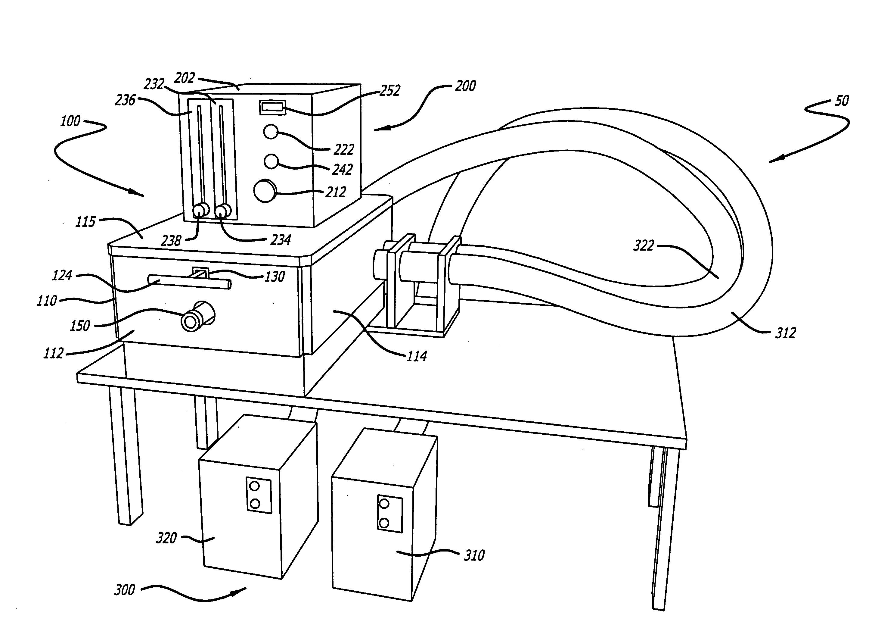
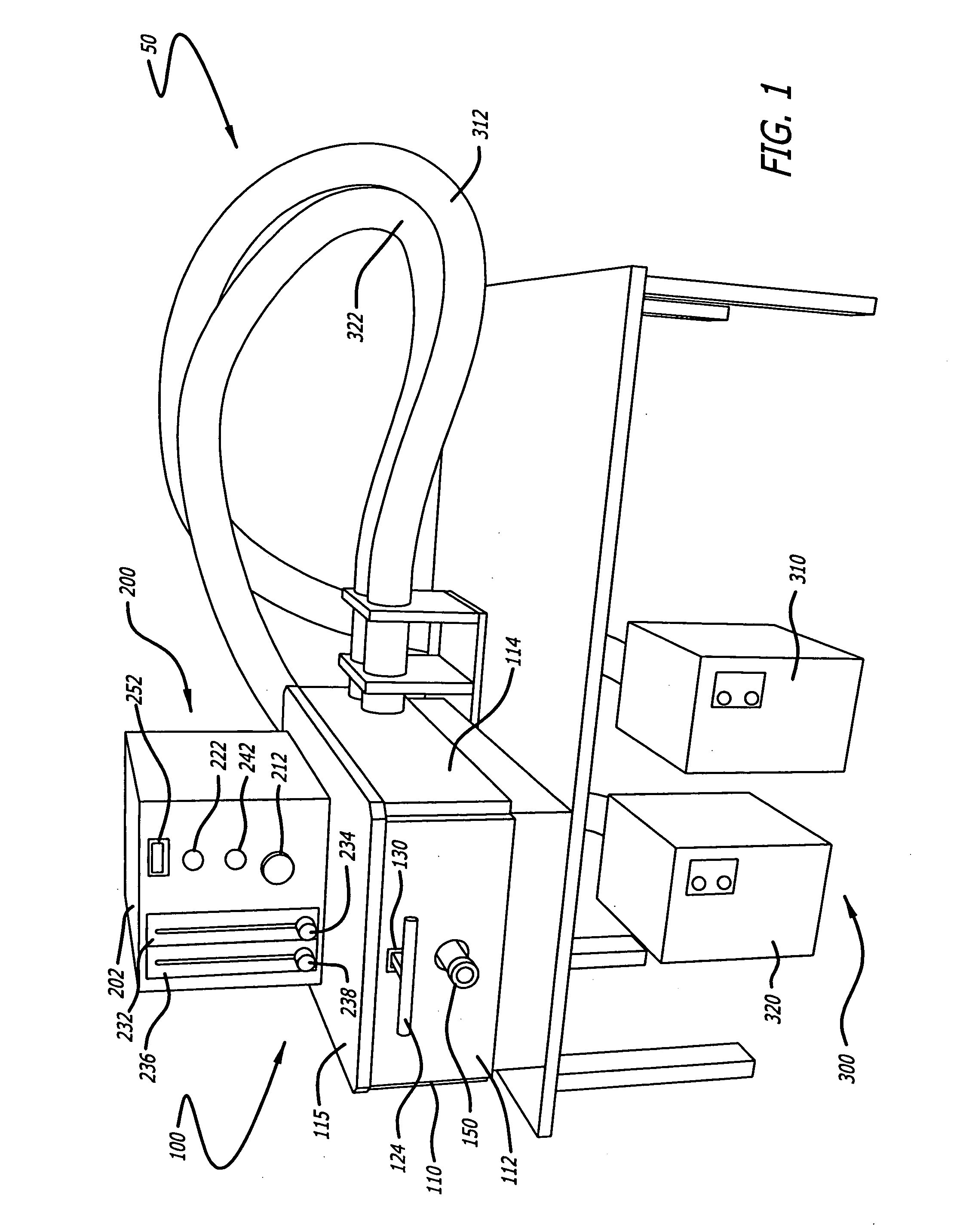
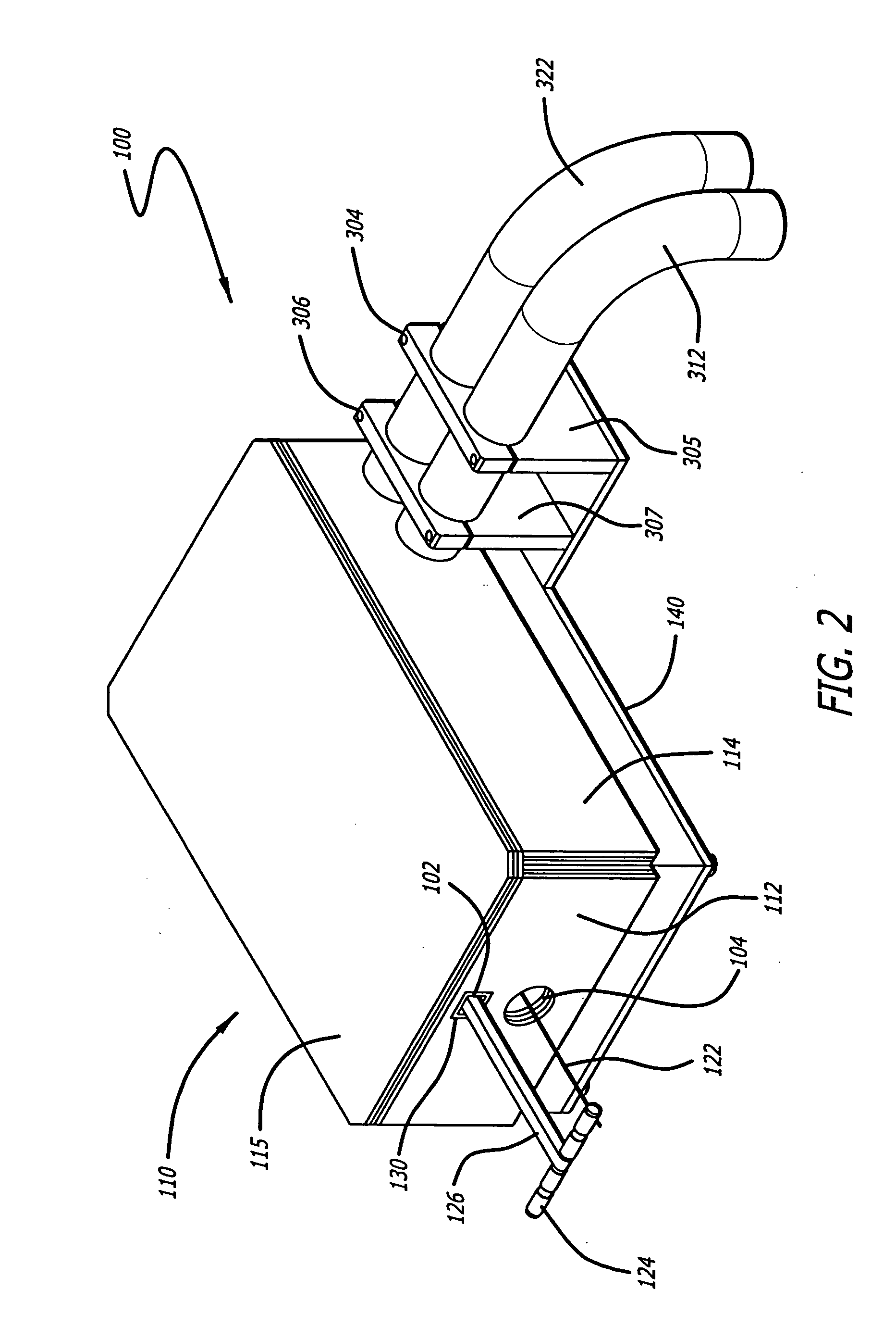
[0046]As shown in FIG. 1, the cold collapser system 50 of the present invention includes a co...


PUM

PropertyMeasurementUnit
Temperatureaaaaaaaaaa

Abstract

A system and method are disclosed for collapsing medical devices, such as self-expanding, drug-eluting stents for loading into delivery catheters. The collapsing apparatus may be used for crimping expandable stents and other devices onto a balloon catheter. The medical device is cooled below the austenitic phase transformation temperature of the material forming the device, such as stainless steel or nitinol, and may be cooled until the material has fully transformed to the martenstitic state. For coated medical devices, the device is warmed to a temperature just below the beginning of austenite phase transformation prior to collapsing. An apparatus having a plurality of offset blades, linear bearings, radial bearings and an actuator mechanism is provided for collapsing the medical device. The system is configured with a mandrel subassembly to push the medical device into a catheter sheath, and with a nozzle subassembly to direct cold gas to the medical device.

Description

BACKGROUND OF THE INVENTION[0001]The present invention relates to an apparatus and method for collapsing a device, and more specifically for collapsing an intraluminal medical device, such as a stent or an embolic filter. The device may be collapsed and placed into a sheath or crimped onto the distal end of a delivery catheter or balloon catheter, such as those used, for example, in percutaneous transluminal coronary angioplasty (PTCA) procedures or in percutaneous transluminal angioplasty (PTA) procedures. The present invention may be adapted for collapsing or crimping balloon expandable stents and self-expanding stents, such as those made from nickel-titanium alloys (nitinol).[0002]As used herein, the term “proximal” is used as the end or portion that is closest to the user (for example, from the outside of the containment housing), and the the term “distal” is used as the end or portion that is furthest from the user (for example, towards the inside of the containment housing). A...

Claims


Application Information

Patent Timeline
IPC IPC(8): B21J7/16
CPCA61F2/95F25D3/10A61F2002/9522A61F2/9522A61F2/9526
Inventor GILLICK, MATTHEW J.PAPP, JOHN E.
Owner ABBOTT CARDIOVASCULAR
Learn More